SPECIFICATIONS
Material
Torque Specifications
a Refer to the procedure in this section.
DESCRIPTION AND OPERATION
Fuel Charging and Controls
3.5L Gasoline Turbocharged Direct Injection (GTDI)
WARNING: Do not smoke, carry lighted tobacco or have an open flame of any type when working on or near any fuel-related component. Highly flammable mixtures are always present and may be ignited. Failure to follow these instructions may result in serious personal injury.
NOTICE: Handle the fuel injectors and fuel rail with extreme care to prevent damage to the fuel inlet of the fuel rail, fuel injector sealing areas, and sensitive fuel-metering orifices.
Component Description
Refer to PC/ED manual section 1 Description and Operation.
System Operation
Refer to PC/ED manual section 1 Description and Operation.
Fuel Charging and Controls Component Location
- Refer to Fuel Injection Pump.
- Refer to Fuel Pump Control Module.
- Refer to Fuel Rail and Fuel Injector - Exploded View.
- Refer to Throttle Body - 3.5L GTDI.
DIAGNOSIS AND TESTING
Fuel Charging and Controls
For PCM DTCs, REFER to Section 303-14, PCM DTC Chart. For driveability symptoms without DTCs, refer to the Powertrain Control/Emissions Diagnosis (PC/ED) manual, section 3 Symptom Charts.
GENERAL PROCEDURES
Fuel Injection Pump Roller Tappet Inspection
- Inspect the fuel injection pump tappet for flat spots or scoring. If any damage is found, inspect the fuel injection pump and the fuel injection pump tappet drive lobe. Install new components as necessary.
REMOVAL AND INSTALLATION
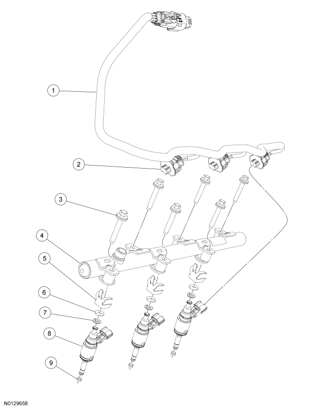
Fuel Rail and Fuel Injector - Exploded View
3.5L GTDI LH Fuel Rail and Fuel Injectors
3.5L GTDI RH Fuel Rail and Fuel Injectors
- Refer to the procedures and/or exploded views in this section for any Warnings, Notices, Notes, Materials, Specifications, and Special Tools. Items in the exploded views may not be listed in order of removal.
Fuel Injectors
Removal and Installation
- The fuel injectors are serviced with the fuel rail. For additional information, refer to Fuel Rail - 3.5L GTDI in this section.
Fuel Rail - 3.5L GTDI
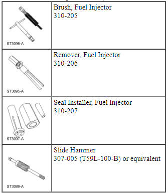
Special Tool(s)
Material
Removal
WARNING: Do not smoke, carry lighted tobacco or have an open flame of any type when working on or near any fuel-related component. Highly flammable mixtures are always present and may be ignited. Failure to follow these instructions may result in serious personal injury.
WARNING: Do not carry personal electronic devices such as cell phones, pagers or audio equipment of any type when working on or near any fuel-related component. Highly flammable mixtures are always present and may be ignited. Failure to follow these instructions may result in serious personal injury.
WARNING: When handling fuel, always observe fuel handling precautions and be prepared in the event of fuel spillage. Spilled fuel may be ignited by hot vehicle components or other ignition sources. Failure to follow these instructions may result in serious personal injury.
WARNING: Before working on or disconnecting any of the fuel tubes or fuel system components, relieve the fuel system pressure to prevent accidental spraying of fuel. Fuel in the fuel system remains under high pressure, even when the engine is not running. Failure to follow this instruction may result in serious personal injury.
WARNING: Clean all fuel residue from the engine compartment. If not removed, fuel residue may ignite when the engine is returned to operation. Failure to follow this instruction may result in serious personal injury.
WARNING: Always disconnect the battery ground cable at the battery when working on an evaporative emission (EVAP) system or fuel-related component. Highly flammable mixtures are always present and may be ignited. Failure to follow these instructions may result in serious personal injury.
NOTE: A clean working environment is essential to prevent dirt or foreign material contamination.
- Release the fuel system pressure. For additional information, refer to Section 310-00.
- Disconnect the battery ground cable. For additional information, refer to Section 414-01.
- Remove the intake manifold. For additional information, refer to Section 303-01B.
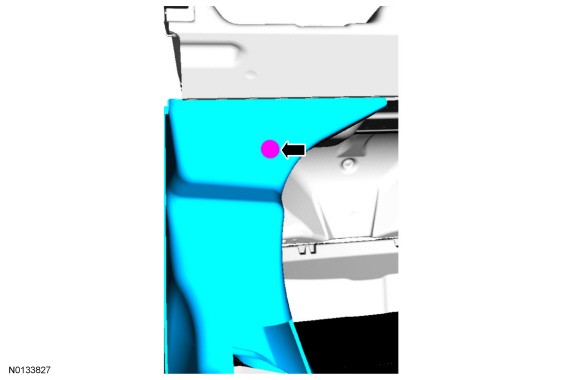
- Remove the fuel injection pump noise insulator shield.
- Remove the high pressure fuel tube bracket nut.
- NOTE: To release the fuel pressure in the high pressure fuel
tube, wrap the flare nuts with a shop towel to absorb any residual fuel
pressure during the loosening of the flare nuts.
Loosen the 3 flare nuts and remove the high pressure fuel tube.
- Disconnect the Fuel Rail Pressure (FRP) sensor electrical connector.
- NOTICE: It is very important to note the routing of the fuel
charge wire harnesses on the fuel rails and index-mark the location of the
tie straps prior to removal or damage may occur to the wire harnesses during
installation.
NOTE: Use compressed air and remove any dirt or foreign material from the cylinder head, block and general surrounding area of the fuel rail and injectors.
Cut, remove and discard the fuel charge wiring harness tie straps.
- NOTICE: Pull out the fuel rails in the direction of the fuel
injector axis or damage may occur to the fuel injectors.
NOTE: When removing the fuel rails, the fuel injectors may remain in the fuel rails but normally remain in the cylinder heads and require the use of a Fuel Injector Remover tool to extract.
Remove and discard the 6 bolts and remove the LH fuel rail.
- Remove and discard the 6 bolts and remove the RH fuel rail.
- Disconnect the 6 fuel injector electrical connectors and remove the 2 fuel charge wire harnesses.
- Remove and discard the 6 upper fuel injector O-ring seals.
- Remove and discard the 6 fuel injector clips.
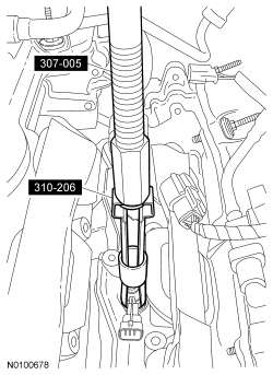
- Using the Slide Hammer and the Fuel Injector Remover, remove the 6 fuel injectors.
Installation
NOTE: A clean working environment is essential to prevent dirt or foreign material contamination.
- NOTE: Make sure to thoroughly clean any residual fuel or foreign
material from the cylinder head, block and the general surrounding area of
the fuel rails and injectors.
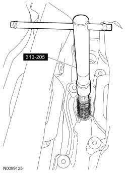
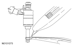
Using the Fuel Injector Brush, clean the fuel injector orifices.
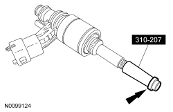
- NOTICE: Do not attempt to cut the lower Teflon seal without
first pulling it away from the fuel injector or damage to the injector may
occur.
NOTE: Be very careful when removing the lower Teflon seals, not to scratch, nick or gouge the fuel injectors.
Pull the lower Teflon seal away from the injector with narrow tip pliers.
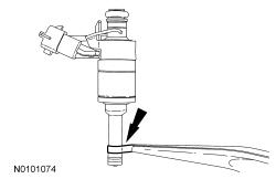
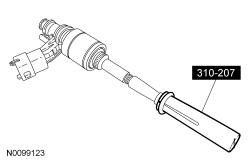
- Carefully cut and discard the 6 lower fuel injector Teflon seals.
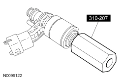
- NOTE: Do not lubricate the 6 new lower Teflon fuel injector
seals.
Install the new lower Teflon seals on the narrow end of the Arbor (part of the Fuel Injector Seal Installer), then install the Arbor on the fuel injector tips.
- NOTICE: Once the Teflon seal is installed on the Arbor, it
should immediately be installed onto the fuel injector to avoid excessive
expansion of the seal.
Using the Pusher Tool (part of the Fuel Injector Seal Installer), slide the Teflon seals off of the Arbor and into the groove on the fuel injectors.
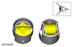
- Place the Adjustment Ring (part of the Fuel Injector Seal Installer)
beveled side first, over the fuel injector tip until it bottoms out against
the fuel injector and turn 180 degrees.
- After one minute, turn the Adjustment Ring back 180 degrees and remove.
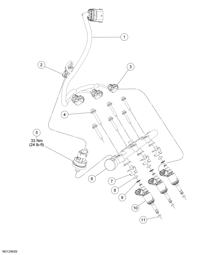
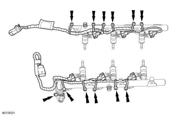
- NOTICE: It is very important to note the routing of the fuel
charge wiring harnesses on the fuel rails and index-mark the location of the
tie straps prior to removal or damage may occur to the wire harnesses during
installation. The illustration details the correct fuel charge wire harness
routing and tie strap positioning for installation.
Install the fuel charge wire harnesses and tie straps to the index-marked locations on the fuel rails. Start by attaching the first tie strap farthest down the wire harness and continue to the connector end of the harness, leaving ample slack between the fuel injectors.
- Connect the FRP sensor electrical connector.
- NOTICE: Use fuel injector O-ring seals that are made of
special fuel-resistant material. The use of ordinary O-ring seals may cause
the fuel system to leak. Do not reuse the O-ring seals.
NOTE: To install, apply clean engine oil to the 6 new upper fuel injector O-ring seals only. Do not lubricate the lower fuel injector Teflon seals.
NOTE: Inspect the fuel injector support disks and replace if necessary.
Install the 6 new upper fuel injector O-ring seals.
- Install the 6 new fuel injector clips.
- NOTE: The anti-rotation device on the fuel injector has to slip
into the groove of the fuel rail cup.
Install the 6 fuel injectors into the fuel rails and connect the 6 electrical connectors.
- NOTICE: It is very important to visually inspect the routing
of the fuel charge wire harness to make sure that they will not be pinched
or damaged between the fuel rail and the cylinder head during installation.
NOTE: Tighten the bolts in a method that draws the fuel rail evenly to the head, preventing a rocking motion.
Install the 6 new bolts and the RH fuel rail assembly.- Push down on the fuel rail face above the injectors and begin tightening the outer bolts first and then proceed inward.
- To install, tighten to 10 Nm (89 lb-in).
- Tighten an additional 45 degrees.
- NOTICE: It is very important to visually inspect the routing
of the fuel charge wire harness to make sure that they will not be pinched
or damaged between the fuel rail and the cylinder head during installation.
NOTE: Tighten the bolts in a method that draws the fuel rail evenly to the head, preventing a rocking motion.
Install the 6 new bolts and the LH fuel rail assembly.- Push down on the fuel rail face above the injectors and begin tightening the outer bolts first and proceed inward.
- To install, tighten to 10 Nm (89 lb-in).
- Tighten an additional 45 degrees.
- NOTE: To install, apply clean engine oil to the threads of the 3
high-pressure fuel tube flare nuts.
Install the high-pressure fuel tube and tighten the 3 flare nuts in the following 3 stages.
- Stage 1: Tighten to 32 Nm (24 lb-ft).
- Stage 2: Wait 10 minutes to minimize pre-stress.
- Stage 3: Tighten to 32 Nm (24 lb-ft).
- Install the high-pressure fuel tube bracket nut.
- Tighten to 8 Nm (71 lb-in).
- Install the fuel injection pump noise insulator shield.
- Install the intake manifold. For additional information, refer to Section 303-01B.
- Connect the battery ground cable. For additional information, refer to Section 414-01.
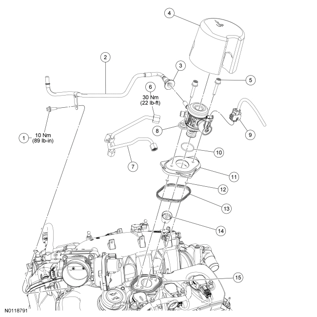
Fuel Injection Pump
Material
Removal
WARNING: Before beginning any service procedure in this section, refer to Safety Warnings in Section 100-00. Failure to follow this instruction may result in serious personal injury.
WARNING: Do not smoke, carry lighted tobacco or have an open flame of any type when working on or near any fuel-related component. Highly flammable mixtures are always present and may be ignited. Failure to follow these instructions may result in serious personal injury.
WARNING: Before working on or disconnecting any of the fuel tubes or fuel system components, relieve the fuel system pressure to prevent accidental spraying of fuel. Fuel in the fuel system remains under high pressure, even when the engine is not running. Failure to follow this instruction may result in serious personal injury.
WARNING: Clean all fuel residue from the engine compartment. If not removed, fuel residue may ignite when the engine is returned to operation. Failure to follow this instruction may result in serious personal injury.
WARNING: Always disconnect the battery ground cable at the battery when working on an evaporative emission (EVAP) system or fuel-related component. Highly flammable mixtures are always present and may be ignited. Failure to follow these instructions may result in serious personal injury.
- Release the fuel system pressure, refer to Section 310-00.
- Disconnect the battery ground cable, refer to Section 414-01.
- Remove the fuel injection pump noise insulator shield.
- Disconnect the fuel injection pump electrical connector.
- Remove the fuel jumper tube bolt.
- NOTE: To release the fuel pressure in the high pressure fuel
tube, wrap the flare nut with a shop towel to absorb any residual fuel
pressure during the loosening of the flare nut.
Disconnect the high pressure fuel tube-to-fuel injection pump flare nut.
- Disconnect the fuel jumper tube-to-fuel injection pump quick connect coupling, refer to Section 310-00.
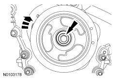
- Remove the 2 bolts and the fuel injection pump.
Installation
- NOTE: The cam lobe for the fuel injection pump must be at Bottom
Dead Center (BDC) for the fuel injection pump installation.
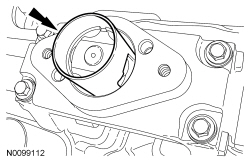
Remove the fuel injection pump roller tappet.
- Inspect the fuel injection pump roller tappet, refer to Fuel Injection Pump Roller Tappet Inspection in this section.
- Remove the fuel injection pump mounting plate.
- Remove the RH front wheel and tire, refer to Section 204-04.
- Position aside the RH fender splash shield, refer to Section 501-02.
- Using the crankshaft pulley bolt, turn the crankshaft until the fuel injection pump cam lobe is at BDC.
- Reposition the RH fender splash shield, refer to Section 501-02.
- Install the RH front wheel and tire, refer to Section 204-04.
- NOTE: The valve cover is removed for clarity.
NOTE: Apply clean engine oil to the fuel injection pump mounting pedestal bore.
Install the fuel injection pump roller tappet.
- NOTE: Apply clean engine oil to the fuel injection pump mounting
plate seal.
Inspect the fuel injection pump mounting plate seal and replace as necessary.
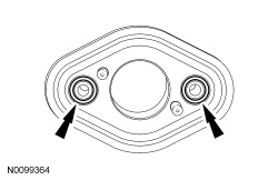
- NOTE: Apply clean engine oil to the fuel injection pump mounting
plate O-ring seals.
Inspect the 2 fuel injection pump mounting plate O-ring seals and replace as necessary.
- NOTE: Apply clean engine oil to the fuel injection pump O-ring
seal.
Inspect the fuel injection pump O-ring seal and replace as necessary.
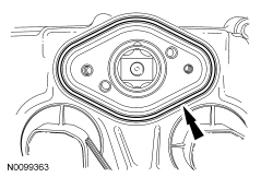
- NOTE: Make sure the mating surfaces are free of any dirt or
foreign material.
NOTE: Apply clean engine oil to the fuel injection pump mounting plate bore.
NOTE: Orient the arrow on the fuel injection pump mounting plate towards the front of the engine.
Install the fuel injection pump mounting plate on the fuel injection pump.
- NOTE: Clean the fuel injection pump bolts and apply Thread
Sealant with PTFE to the bolts.
Install the fuel injection pump with the fuel injection pump mounting plate and loosely install 2 new fuel injection pump bolts, alternately tighten each bolt one complete revolution until seated. Tighten the 2 fuel injection pump bolts in the following 2 stages.
- Stage 1: Tighten to 10 Nm (89 lb-in).
- Stage 2: Tighten an additional 45 degrees.
- NOTE: To install, apply clean engine oil to the threads of the
high-pressure fuel tube flare nut.
Connect the high-pressure fuel tube and tighten the flare nut in the following 3 stages.
- Stage 1: Tighten to 32 Nm (24 lb-ft).
- Stage 2: Wait 10 minutes to minimize pre-stress.
- Stage 3: Tighten to 32 Nm (24 lb-ft).
- Connect the fuel jumper tube-to-fuel injection pump quick connect coupling, refer to Section 310-00.
- Install the fuel jumper tube bolt.
- Tighten to 10 Nm (89 lb-in).
- Connect the fuel injection pump electrical connector.
- Install the fuel injection pump noise insulator shield.
- Connect the battery ground cable, refer to Section 414-01.
Fuel Pump Control Module
Removal and Installation
NOTE: Removal steps in this procedure may contain installation details.
- Fold the RR seat backrest down.
- NOTICE: Do not overtighten the fasteners or damage to the
module will occur.
Tighten to 5 Nm (44 lb-in).
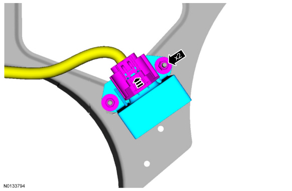
- To install, reverse the removal procedure.
Throttle Body - 3.5L GTDI
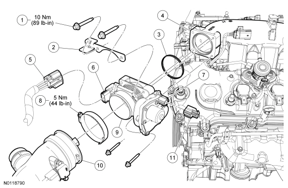
Removal and Installation
- Disconnect the Throttle Position (TP) sensor electrical connector.
- Disconnect the Throttle Actuator Control (TAC) electrical connector.
- Loosen the clamp and disconnect the Charge Air Cooler (CAC) outlet
pipe-to-Throttle Body (TB).
- To install, tighten to 5 Nm (44 lb-in).
- Remove the 4 bolts, the TB and the TP sensor shield bracket.
- Discard the TB gasket.
- To install, tighten to 10 Nm (89 lb-in).
- NOTE: Install a new TB gasket.
To install, reverse the removal procedure.
 Fuel Charging and Controls - 3.5L Ti-VCT
SPECIFICATIONS
Material
Torque Specifications
DESCRIPTION AND OPERATION
Fuel Charging and Controls
Component Locations
WARNING: Do
not smoke, carry lighted tobacco or have an open flame of any type ...
 Fuel Charging and Controls - 2.0L GTDI
SPECIFICATIONS
Material
Torque Specifications
a Refer to the procedure in this section.
DESCRIPTION AND OPERATION
Fuel Charging and Controls
Component Locations
WARNING: Do
not smoke, carry li ...
Other materials:
Engine coolant check
Checking the Engine Coolant
The concentration and level of engine coolant should be checked at the
intervals listed in Scheduled Maintenance Information.
Note: Make sure that the level is at the FULL COLD level or within the
COLD FILL RANGE in the coolant reservoir.
Note: Coolant expands wh ...
Front Disc Brake
SPECIFICATIONS
Torque Specifications
REMOVAL AND INSTALLATION
Brake Pads - 325 mm (13 in) Brakes
Material
Removal
WARNING:
Before beginning any service procedure in this section, refer to Safety Warnings
in Section 100-00. Failure to follow this instruction may result in serious
personal i ...
Exceptions
There are several exceptions to the Normal Schedule. They are listed
below:
Normal vehicle axle maintenance: Rear axles and power take-off
(PTO) units with synthetic fluid and light-duty trucks equipped with
Ford-design axles are lubricated for life; do not check or change fluid
unless a leak i ...
