Wheel and Tire
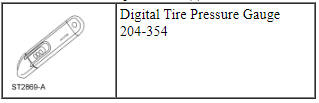
Special Tool(s)
Disassembly
WARNING: The tire pressure monitoring system (TPMS) sensor battery may release hazardous chemicals if exposed to extreme mechanical damage. If these chemicals contact the skin or eyes, flush immediately with water for a minimum of 15 minutes and get prompt medical attention. If any part of the battery is swallowed, contact a physician immediately. When disposing of TPMS sensors, follow the correct procedures for hazardous material disposal. Failure to follow these instructions may result in serious personal injury.
NOTICE: Failure to follow the instructions below may result in damage to the Tire Pressure Monitoring System (TPMS) sensor.
NOTICE: The Tire Pressure Monitoring System (TPMS) sensor is mounted to the valve stem. Removal of the valve stem requires dismounting the tire from the wheel and removal of the TPMS sensor.
NOTE: Use only the Digital Tire Pressure Gauge any time tire pressures are measured to be sure that accurate values are obtained.
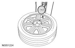
- Remove the wheel and tire. For additional information, refer to Wheel and Tire in this section.
- NOTICE: The valve stem is connected to the Tire Pressure
Monitoring System (TPMS) sensor. Do not pull the valve stem from the wheel,
or damage to the sensor will occur.
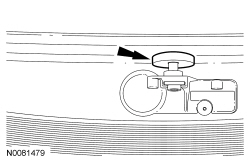
Remove the valve stem core and fully deflate all air from the tire.
- If a new Tire Pressure Monitoring System (TPMS) sensor is being installed, remove and discard the valve stem-to-sensor screw and the sensor.
NOTICE: Do not allow the tire beads to move beyond the wheel mid-plane (middle of the wheel) when separating the beads from the wheels, damage to the Tire Pressure Monitoring System (TPMS) sensor may occur.
- NOTICE: Tire and valve stem position is critical to prevent
damage to the Tire Pressure Monitoring System (TPMS) sensor when using a
paddle-type bead separator.
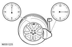
NOTE: Some machines may have a nylon roller bead separator at the 12 o'clock position instead of the paddle-type bead separator at the 3 o'clock position.
Position the wheel and tire assembly on a suitable tire machine and separate both beads of the tire from the wheel.- For a paddle-type tire machine, position the valve stem at the 12 o'clock or 6 o'clock position and the paddle at the 3 o'clock position.
- For a roller-type tire machine, align the valve stem with the roller at any position.
- NOTE: Index-mark the valve stem and wheel weight positions on the
tire.
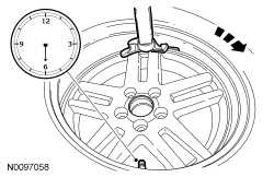
Place the wheel and tire assembly on the turntable of the tire machine with the valve stem at the 11:30 position and the machine arm at the 12 o'clock position and dismount the outer bead from the wheel.
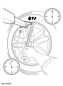
- Reset the wheel and tire assembly on the turntable of the tire machine with the valve stem at the 11:30 position and the machine arm at the 12 o'clock position and dismount the inner bead from the wheel.
- NOTE: A new valve stem must be installed whenever a new tire or
wheel is installed.
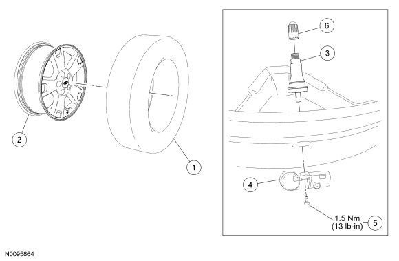
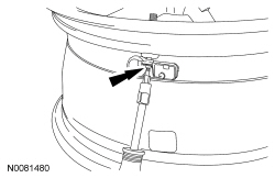
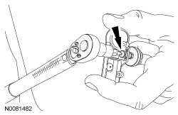
Remove the TPMS sensor in the following sequence.
- Using a T10 Torx, remove the valve stem-to- TPMS sensor screw.
- Carefully and firmly, pull the sensor straight down and separate it from the valve stem.
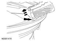
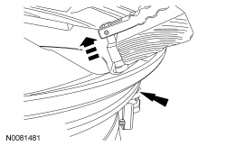
- NOTICE: Use care not to damage the wheel surface when removing
the valve stem.
Using a suitable valve stem puller and a wood block, remove the valve stem from the wheel.
- NOTE: When installing a new wheel, always install a new valve
stem and sensor screw. Reuse the TPMS sensor from the previous wheel if
possible. The TPMS will not have to be trained if the sensor is reused.
If the TPMS sensor is being reused, inspect the TPMS sensor for damage and install a new sensor as necessary.
Assembly
NOTICE: Damage to the Tire Pressure Monitoring System (TPMS) sensor may result if the tire mounting is not carried out as instructed.
- NOTICE: To prevent Tire Pressure Monitoring System (TPMS)
sensor and valve stem damage, the valve stem must be installed onto
the TPMS sensor and then installed into the wheel as an assembly.
Install a new valve stem onto the TPMS sensor.
- Tighten the new valve stem-to- TPMS sensor screw to 1.5 Nm (13 lb-in).
- NOTICE: It is important to pull the valve stem and Tire
Pressure Monitoring System (TPMS) sensor assembly through the wheel rim hole
in a direction parallel to the valve stem hole axis. If the assembly is
pulled through at an angle, damage to the valve stem and sensor assembly may
occur.
NOTICE: Use care not to damage the wheel surface when installing the valve stem and Tire Pressure Monitoring System (TPMS) sensor assembly.
Lubricate the valve stem with soapy water and install the valve stem and TPMS sensor assembly into the wheel using a block of wood and a suitable valve stem installer.
- Make sure the valve stem rubber is fully seated against the wheel.
- NOTE: Lubricate the tire beads using a suitable fast-drying,
corrosion-inhibiting tire bead lubricant.
NOTE: Do not mount the tire at this time.
Position the wheel on the turntable of the tire machine, then lubricate and position the bottom bead of the tire on the wheel.
- Position the wheel to align the valve stem with the machine arm, at the 6 o'clock position, and mount the bottom bead of the tire.
- Reposition the wheel to align the valve stem with the machine arm at the 6 o'clock position, and mount the top bead of the tire.
- NOTE: Use only the Digital Tire Pressure Gauge any time tire
pressures are measured to make sure that accurate values are obtained.
Inflate the tire to the pressure specified on the Vehicle Certification (VC) label located on the driver door or door pillar.
- Proceed to Step 8 if the tire beads do not seat at the specified inflation pressure.
- WARNING:
If there is a need to exceed the maximum pressure indicated on the sidewall
of the tire in order to seat the beads, follow all steps listed below.
Failure to follow these steps may result in serious personal injury.
The following steps should only be carried out if the tire beads cannot be seated by inflating the tire up to the maximum inflation pressure listed on the tire sidewall.
- Relubricate the tire bead and wheel bead seat area.
- Install a remote valve and pressure gauge.
- Wear eye and ear protection and stand at a minimum of 3.65 m (12 ft) away from the wheel and tire assembly.
- Inflate the tire using the remote valve and tire gauge until the beads have seated or until the pressure gauge is 138 kPa (20 psi) more than maximum inflation pressure on tire sidewall. If beads have not seated, deflate the tire and proceed to the next step.
- Place the wheel and tire assembly in an OSHA-approved tire safety cage.
- Inflate the tire using the remote valve and pressure gauge until the beads have seated or until the pressure gauge is 276 kPa (40 psi) more than maximum inflation pressure on the tire sidewall. Do not exceed 276 kPa (40 psi) above the maximum pressure on tire sidewall. Install a new tire if the beads do not seat at this pressure.
- Install the wheel and tire. For additional information, refer to Wheel and Tire in this section.
DISASSEMBLY AND ASSEMBLY OF SUBASSEMBLIES
Tire Pressure Monitoring System (TPMS) Sensor
Disassembly
- NOTE: The Tire Pressure Monitoring System (TPMS) sensor cannot be
removed without disassembly of the wheel and tire.
Disassemble the wheel and tire. For additional information, refer to Wheel and Tire in this section.
 General Procedures, Removal and Installation
GENERAL PROCEDURES
Tire Pressure Monitoring System (TPMS) Sensor Training - Integrated Keyhead
Transmitter (IKT)
Special Tool(s)
NOTE: If the vehicle has been stationary for more than 30 minute ...
 Driveline
...
Other materials:
Heated windows and mirrors (if equipped)
Heated Rear Window
Note: The ignition must be switched on to use this feature.
Press the button to clear the rear window of thin ice and fog. Press the
button again within 10 minutes to switch it off. It switches off
automatically after 10 minutes, or when you switch the ignition off.
Do no ...
Installation
Engine
Special Tool(s)
Material
All vehicles
Using the Floor Crane and Spreader Bar, align the transaxle to the
engine.
Align the transaxle to the engine and install the 5 transaxle-to-engine
bolts.
Tighten to 48 Nm (35 lb-ft).
Install the 2 engine-to-transaxle bolts.
...
Noise, Vibration and Harshness (NVH) - Diagnosis and Testing
Special Tool(s)
Diagnostic Theory
The shortest route to an accurate diagnosis results from:
system knowledge, including comparison with a known good system.
system history, including repair history and usage patterns.
condition history, especially any relationship to repairs or sudden
change ...
