Seating
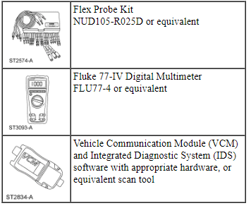
Special Tool(s)
Medium Speed Controller Area Network (MS-CAN)
This vehicle utilizes a communication system called a Medium Speed Controller Area Network (MS-CAN). When diagnosing the memory seat, heated seats or climate controlled seats, use a Vehicle Communication Module (VCM) and Integrated Diagnostic System (IDS) software with appropriate hardware, or equivalent scan tool with the latest software update with the capability of communicating over the MS-CAN bus.
Principles of Operation
Driver and Passenger Power Seats Without Memory
The 6-way power seat track can be moved forward or backward and the front and back of the cushion can be moved up and down independently.
The 10-way power seat track can be moved forward or backward and the front and back of the cushion can be moved up and down independently. The backrest of the seat can be moved forward and backward. The lumbar can be moved in and out.
The 14-way power seat track can be moved forward or backward and the front and back of the cushion can be moved up and down independently. The backrest of the seat can be moved forward and backward. The lumbar can be moved in and out, up and down or can massage. The seat cushion can also massage. All modes of operation are controlled by one switch. Refer to Seating in this section for switch and system operation.
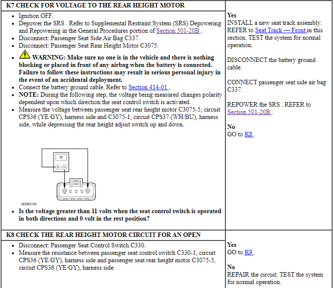
The power seat track, recline and stand alone power lumbar motors operate independent of ignition position. Power lumbar with backrest and cushion massage require the engine to be running. The power seat motors and lumbar control module are hardwired to the seat control switch. The circuits are normally at ground through the seat control switch. An individual circuit is switched to voltage when a specific adjustment position is selected.
Power Driver Seat With Memory
NOTE: Verify good battery condition before diagnosing the memory seat system. Poor battery condition may interfere with memory seat operation, even if vehicle starting is possible.
NOTE: A memory recall in progress does not prohibit the initiation of another memory recall; the most recently requested memory recall will be executed.
The 10-way power seat track can be moved forward or backward and the front and back of the cushion can be moved up and down independently. The backrest of the seat can be moved forward and backward. The lumbar can be moved in and out.
The 14-way power seat track can be moved forward or backward and the front and back of the cushion can be moved up and down independently. The backrest of the seat can be moved forward and backward. The lumbar can be moved in and out, up and down or can massage. The seat cushion can also massage. All modes of operation are controlled by one switch. Refer to Seating in this section for switch and system operation.
The power seat track, recline and stand alone power lumbar motors operate independent of ignition position. Power lumbar with backrest and cushion massage require the engine to be running. The power seat motors and lumbar control module are hardwired to the seat control switch. The circuits are normally at ground through the seat control switch. An individual circuit is switched to voltage when a specific adjustment position is selected.
The driver power memory seat is controlled by the Driver Seat Module (DSM). The memory seat feature allows the driver to program a personalized seat position that can be recalled using the memory switch or a Remote Keyless Entry (RKE) transmitter. There are 2 memory settings possible. The 2 settings consist of 8 possible directions: the seat can be moved forward or backward and the front and back of the cushion can be moved up and down independently. The backrest of the seat can be moved forward and backward. Adjustable lumbar is not a memory option. The power seat feature operates independent of the ignition position.
The driver seat control switch provides voltage to the DSM when activated. The NEUTRAL position of the driver seat control switch position is a ground state through the seat control switch contacts. A voltage input causes the DSM to power the appropriate motor until the input is removed. Ground is the normal state of the motor circuits through the DSM and is not switched to control the motors. The DSM internally switches the appropriate circuit from ground to voltage for operating the motors.
As the seat is adjusted, the DSM constantly monitors the motor position sensors to record the current seat position. The DSM will remove voltage from the motor upon termination of the seat control switch input or if the DSM does not see movement from the motor by monitoring the position sensor.
The DSM communicates DTCs and other information using the MS-CAN communication bus. It should be noted for diagnostics that because MS-CAN bus communication is more robust and reliable than other methods, it may be possible to have limited module communication with one of the MS-CAN bus circuits disconnected or shorted to ground. Refer to Section 418-00 for information concerning MS-CAN bus communication.
For information on programming memory positions or recalling a stored memory position, refer to Memory Position Programming in this section. For information on RKE transmitter programming, refer to Section 501-14B.
The DSM is located under the driver seat. To install a new DSM, refer to Driver Seat Module (DSM). Programmable Module Installation (PMI) must be carried out when installing a new DSM. Refer to Section 418-01.
This section only diagnoses concerns specific to the memory seat.
Easy Exit/Easy Entry
The easy entry/exit feature is a function of the DSM. When the ignition key is removed or for vehicles equipped with passive entry/passive start, when the button is pushed to turn the ignition off, the driver seat moves backward a maximum of 51 mm (2 in) or to the soft stop. The DSM receives a key out command over the MS-CAN communication network and powers the driver seat rearward. The DSM will cancel this operation if a valid input command is received from the driver seat control switch, memory SET switch, exterior mirror control switch or adjustable pedal control switch.
The DSM will record the current seat position before powering the seat for an easy exit function. This recorded position will be used to return the seat to this position on the easy entry operation. During easy entry operation, the seat is returned to the position previous to the easy exit operation when the key is inserted into the ignition lock cylinder or for vehicles equipped with passive entry/passive start, the ignition button is pressed. Easy entry operation will be cancelled if a valid input command is received by the DSM.
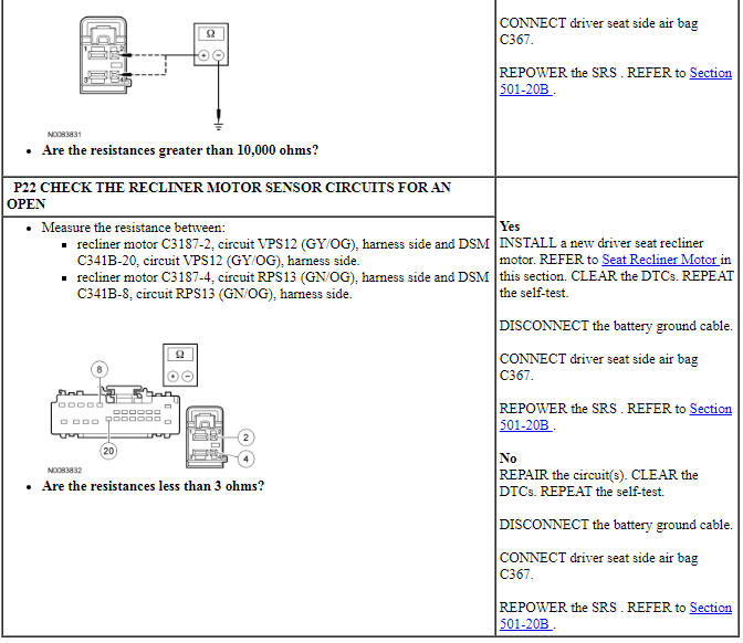
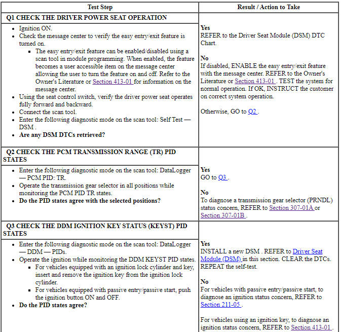
The easy entry/exit feature can be enabled/disabled using a scan tool. When enabled, the feature becomes a user accessible item on the message center allowing the user to turn the feature on and off. Refer to the Owner's Literature or Section 413-01 for information on the message center.
Driver Seat Module (DSM) Hard Stop/Soft Stop
A hard stop occurs when a memory seat track or backrest (recline) axis physically reaches the end of travel and can go no further. A soft stop occurs when the seat stops before physically reaching the end of travel. The hard stop is set by seat design and cannot be changed or adjusted. The soft stop is set by the DSM. To prevent unnecessary stress on the seat, the DSM will set up to 8 soft stop positions, 2 for each moving axis. The seat track axes are forward/backward, front up/down and rear up/down. The seat backrest axis is forward/backward. The DSM will use a preset distance from the hard stop to determine where the soft stop will occur. When an axis reaches the hard stop and the switch is held for approximately one second, it will then back up 180 ms and establish the soft stop for that axis in that direction. The DSM uses this "back up" strategy to check sensor integrity any time movement has stopped prematurely due to a sensor failure or obstruction.
When a new driver seat track with memory or recliner motor, or a DSM has been installed, operate the seat in all directions through the full range of travel to set soft stops and avoid a premature stopping point occurrence after the vehicle is returned to the customer.
Power Lumbar With Cushion and Backrest Massage
Each front seat functions independently of each other. The lumbar control module is located in the seat backrest. The system will function only with the engine running. The lumbar control module does not report DTCs and does not communicate on the CAN. The button pushed on the seat control switch will determine what function the module will carry out. When an individual circuit is switched to voltage, the lumbar control module will carry out a function.
The pump supplies air pressure through a hose to the lumbar control module. The module then directs the air through multiple hoses to the appropriate cushion or backrest pillow.
Refer to Seating in this section for switch and system operation.
Heated Seats - Front
The driver and passenger heated seat control buttons and indicators are located on the Front Controls Interface Module (FCIM). The heated seat system functions independently of the climate control system. Each time the heated seat button is pressed, the FCIM sends the request message to the HVAC module which decreases one setting (the sequence is hi, low, OFF, hi, etc.). For vehicles without a touchscreen interface, when a heated seat is set to hi, both LED indicators above that heated seat's control button illuminate. When a heated seat is set to low, only one LED indicator above that switch illuminates. When off, no indicators illuminate.
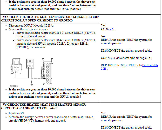
When activated, the HVAC module supplies voltage to the selected seat heater circuit. Each seat cushion heater mat and backrest heater mat is connected in a series circuit to the HVAC module and powered by the output circuit for that seat. The HVAC module monitors inputs from a temperature sensor located in each seat cushion heater mat, and maintains seat temperature by cycling the heater circuits on/off. The heated seat remains ON until the heated seat switch button is pressed to cycle the HVAC module OFF or the ignition is set to OFF.
If a fault is detected by the HVAC module, the module stops supplying voltage to that individual left or right seat that the fault was detected on until the ignition is turned OFF and then ON.
Heated Seats - Rear
Vehicles equipped with rear heated seats are equipped with a single-heated seat module to control both rear heated seats. The heated seat module does not time out. The system will function with the ignition in RUN, whether the engine is running or not. The heated seat module supplies voltage to the heater mats and regulates seat temperature by monitoring a thermostat located in the cushion heater mat.
The heated seat buttons are located in the rear panel of the front floor console. When a heated seat button is pressed, a momentary ground is sent to the heated seat module to turn the heated seat on or off. Pressing the high or low button once turns the heated seat on and pressing the same button a second time turns it off. The heated seat module will send voltage to the separate indicator circuit at the heated seat switch to indicate an on state. The heated seat module will remain on until the heated seat switch is pressed for that high or low mode currently on, sending a second momentary ground signal to the heated seat module or the ignition is set to OFF.
When the heated seat module is on, it provides voltage to the separate indicator circuit at the heated seat button to indicate an on state.
The heated seat module does not report DTCs and does not communicate on the CAN. If a fault is detected, the module will disable the affected seat(s) and indicator(s).
After the fault is corrected, the heated seat module needs to be reset by cycling the ignition OFF and then ON. After the heated seat module has been reset, the module will return to an off state.
Climate Controlled Seat System
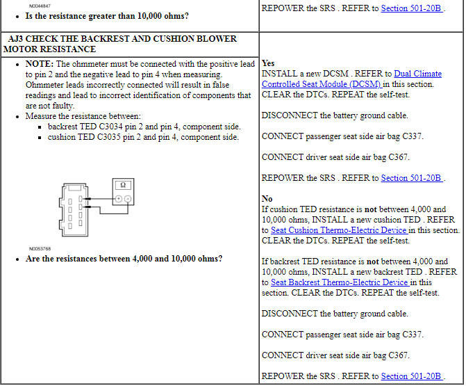
NOTICE: Avoid applying voltage directly to a Thermo-Electric Device (TED) for testing its operation. Doing so may cause damage to the TED.
NOTE: When installing a new Dual Climate Controlled Seat Module (DCSM), it is necessary to carry out Programmable Module Installation (PMI). Refer to Section 418-01.
Both the driver and front passenger climate controlled seats are independently controlled by the DCSM. The climate controlled seat system only operates with the engine running above 350 rpm, however, if using a scan tool to command the DCSM, diagnostic testing can be carried out with the ignition on and engine off. The DCSM does not time out. The DCSM receives voltage from the Battery Junction Box (BJB) on 2 redundant circuits. If one pin does not receive voltage, both seats will remain operational because the voltage supply circuits are internally connected in the DCSM.
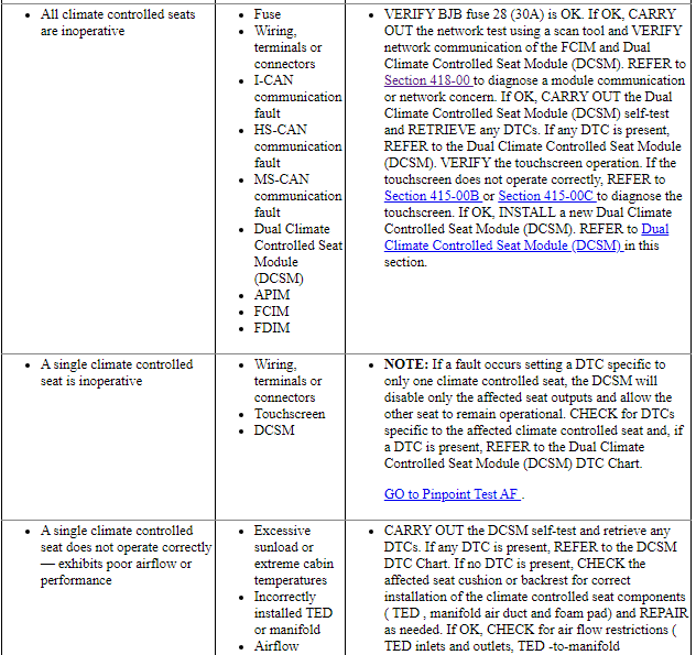
If a fault occurs setting a DTC, only the affected seat will be disabled by the module. If the system shuts down due to a DTC fault, cycling the ignition OFF and then ON again will reset the DCSM to function until the DTC resets.
Each driver and front passenger seat cushion and backrest is equipped with a TED and blower motor assembly. Voltage is applied to the TED to heat/cool the seat. Applying voltage polarity to the TED in one direction causes the TED to heat. Applying voltage polarity in the opposite direction causes the TED to cool. Cabin air is drawn through the blower and distributed to each of the TED modules located in the seat cushion and backrest. The TEDs then heat or cool the incoming air depending on the control switch settings. The air is then directed into the foam pad and manifold where it is distributed along the surface of the cushion and backrest of the seat. Once activated, the DCSM maintains the heating/cooling modes until deactivated.
The temperature differences between the individual heated and cooled settings is minimal. For example, it is difficult to distinguish between low cool and medium cool settings. Measuring seat temperature at different settings is possible by monitoring the DCSM PIDs using the scan tool.
When the climate control seat buttons are activated on the touchscreen interface, the APIM sends the climate controlled seat commands to the FCIM using the I-CAN. The FCIM sends the request message to the IPC using the I-CAN. The IPC sends the request message to the BCM over the HS-CAN. Finally the BCM sends the communicates climate controlled seat commands to the DCSM using the MS-CAN. The MS-CAN is connected to the DLC for diagnostic use. No direct connection exists between the DCSM and touchscreen interface for the climate controlled seat buttons. The climate controlled seats can be commanded on or off using the scan tool to verify both module communication on the MS-CAN and operation of the DCSM. This method may be useful for isolating a control switch concern. Refer to Section 418-00 for additional information concerning CAN.
The climate controlled seats can be commanded using the diagnostic tool to verify both module communication on the MS-CAN bus and operation of the DCSM. This method may be useful for isolating a control switch concern. It should also be noted that because MS-CAN bus communication is more robust and reliable than other methods, it may be possible to have limited module communication with one of the MS-CAN bus circuits disconnected or shorted to ground. Refer to Section 418-00 for information concerning MS-CAN bus communication.
Heating Characteristics
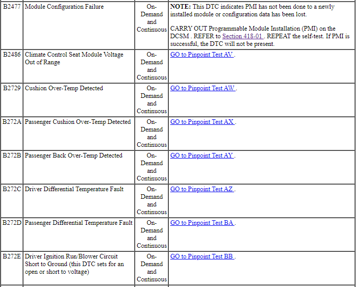
NOTE: The presence of overtemperature faults (DTCs B2729, B2730, B272A and B272B) can be induced by incorrect operation of the climate controlled seat system after an initial HEAT setting has been attained. If a HEAT setting is repeatedly turned OFF and ON in an attempt to increase the seat temperature, an overtemperature condition can result and the DTCs will be set.
- In the LOW setting, the DCSM is set to maintain TED temperature at approximately 47ÂşC (117ÂşF).
- In the MEDIUM setting, the DCSM is set to maintain TED temperature at approximately 55ÂşC (131ÂşF)
- In the HIGH setting, the DCSM is set to maintain TED temperature at approximately 62ÂşC (144ÂşF).
- When heating, the DCSM will vary the speed of the fans and the TED duty cycle in order to reach and maintain the temperature determined by the switch setting.
Cooling Characteristics
- In cool mode, the TED circuits of a given seat are wired in series internally in the DCSM.
- In cool mode, the TED can remove up to 8ÂşC (14ÂşF) from the ambient air temperature entering the system.
- When cooling, the DCSM maintains constant fan speed and TED supply voltage (duty cycle) in open loop cool mode.
Climate Controlled Seat System Recovery Mode
NOTE: The presence of overtemperature faults (DTCs B2729, B2730, B272A and B272B) can be induced by incorrect operation of the climate controlled seat system after an initial heat setting has been attained. If a heat setting is repeatedly turned OFF and ON in an attempt to increase the seat temperature or repeatedly toggled between heat and cool modes, an overtemperature condition can result and the DTCs will be set.
If the temperature at one of the TEDs rises above 110ÂşC (230ÂşF) in the heat mode or 65ÂşC (149ÂşF) in the cool mode for more than 4 seconds, the DCSM will record an overtemperature DTC, remove voltage from the TEDs and go into recovery mode (blower only) for 30 seconds to cool down the TEDs. The same will occur if a temperature difference of 60ÂşC (108ÂşF) or greater is seen between the backrest and cushion TEDs on either front seat. The DCSM will continue to monitor the TEDs while in recovery mode. If the temperature of the TEDs does not drop to 105ÂşC (221ÂşF) in the heat mode or 60ÂşC (140ÂşF) in the cool mode after 30 seconds, the system will continue to cool the TEDs in recovery mode for up to 5 minutes. If the TEDs cool down at anytime after 30 seconds, but before 5 minutes (checked at 4-second intervals), the system will operate as normal. An overtemperature DTC will still be recorded even if the system recovers and is operating normally. Recovery mode is more likely to occur during extreme cabin temperatures with significant seat back sunload. If the system does not recover within 30 seconds in heat mode or within 5 minutes in cool mode, the DCSM will disable that seat (fault mode) and remain off until the ignition is cycled. Also, if the DCSM detects temperature differential fault twice during the same ignition cycle, it will shutdown. When a fault causes a shutdown, the climate controlled seat indicators will turn off for the affected seat and that seat will not be operational until the next key cycle.
Inspection and Verification
- Verify the customer concern.
- Visually inspect for obvious signs of mechanical and electrical damage.
Visual Inspection Chart
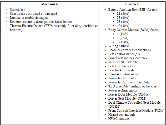
- If an obvious cause for an observed or reported concern is found, correct the cause (if possible) before proceeding to the next step.
- If the concern is with the power seat (non-memory seat) or heated seat and the cause is not visually evident, verify the symptom and GO to Symptom Chart.
- NOTE: Make sure to use the latest scan tool software release.
If the concern is with the memory seat or climate controlled seat and the cause is not visually evident, connect the scan tool to the Data Link Connector (DLC).
- NOTE: The Vehicle Communication Module (VCM) LED prove out
confirms power and ground from the DLC are provided to the VCM.
If the scan tool does not communicate with the VCM :
- check the VCM connection to the vehicle.
- check the scan tool connection to the VCM.
- refer to Section 418-00, No Power To The Scan Tool, to diagnose no power to the scan tool.
- If the scan tool does not communicate with the vehicle:
- verify the ignition is in the ON position.
- verify the scan tool operation with a known good vehicle.
- refer to Section 418-00 to diagnose no response from the PCM.
- Carry out the network test.
- If the scan tool responds with no communication for one or more modules, refer to Section 418-00.
- If the network test passes, retrieve and record Continuous Memory Diagnostic Trouble Codes (CMDTCs).
- Clear the continuous DTCs and carry out the self-test diagnostics for the Driver Seat Module (DSM), Driver Door Module (DDM), DCSM, FCIM and HVAC module.
- If the DTCs retrieved are related to the concern, go to Driver Door Module (DDM) DTC Chart, Driver Seat Module (DSM) DTC Chart, Dual Climate Controlled Seat Module (DCSM) DTC Chart or HVAC Module DTC Chart. For all other DTCs, refer to Section 419-10.
- If no DTCs related to the concern are retrieved, GO to Symptom Chart.
DTC Charts
Driver Door Module (DDM) DTC Chart
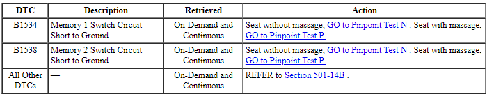
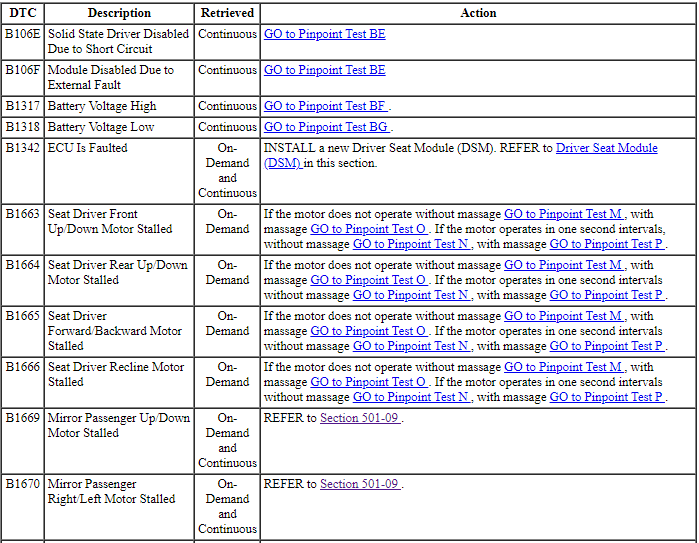
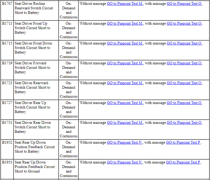
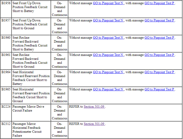
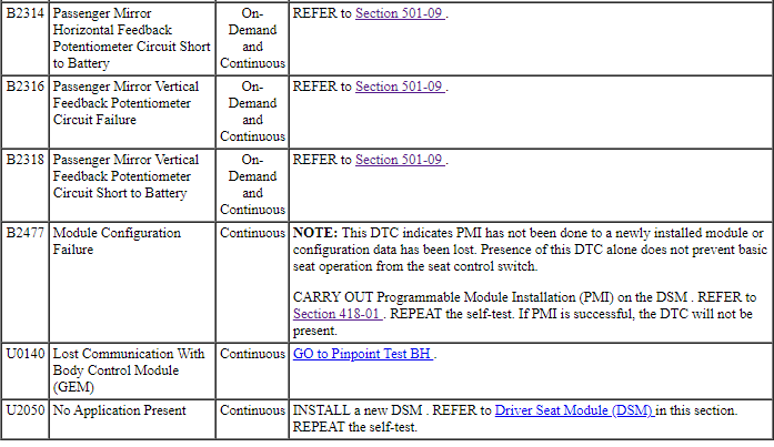
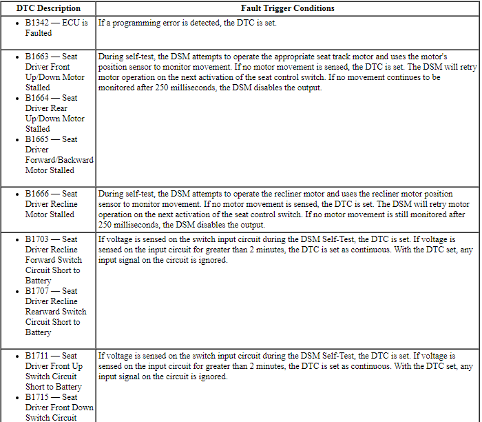
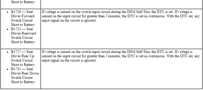
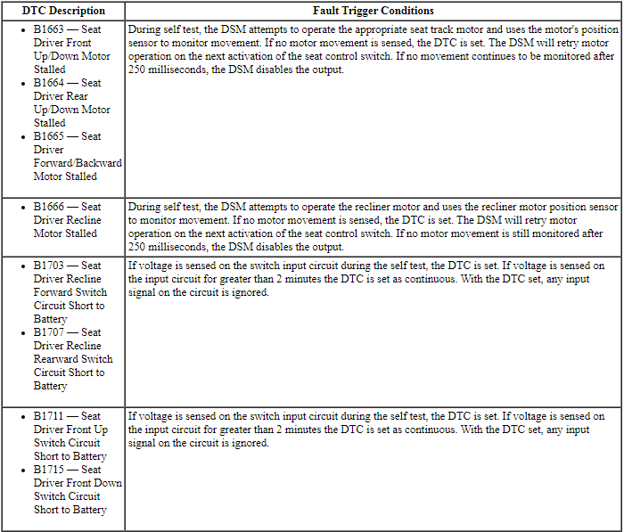
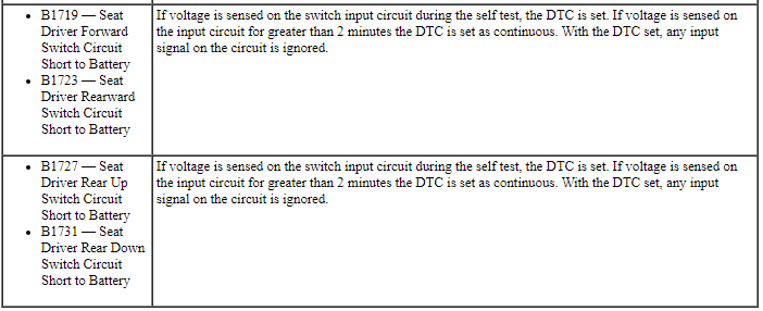
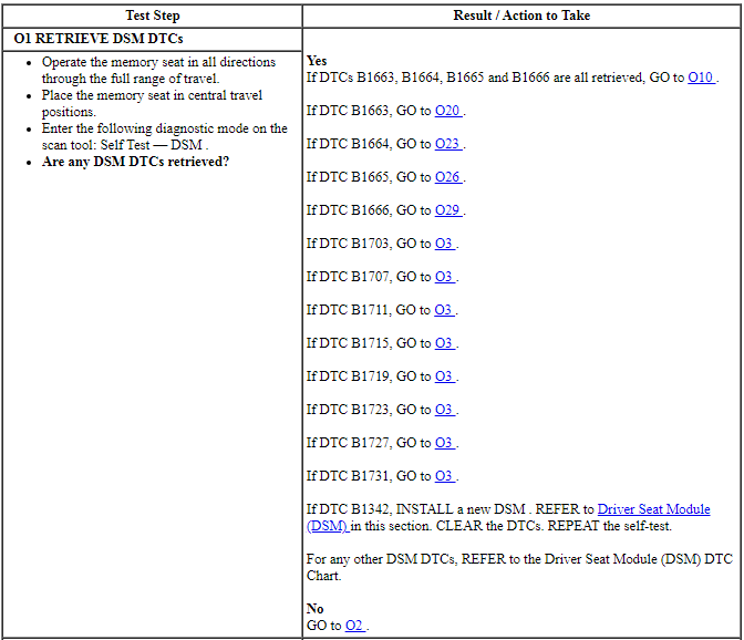
Driver Seat Module (DSM) DTC Chart
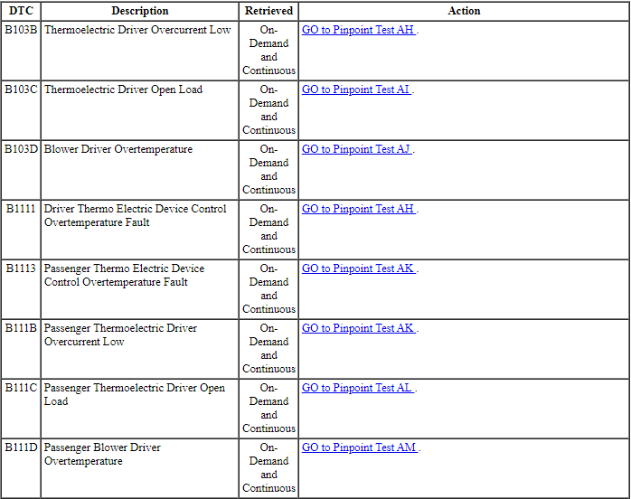
Dual Climate Controlled Seat Module (DCSM) DTC Chart
HVAC Module DTC Chart
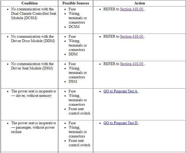
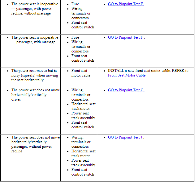
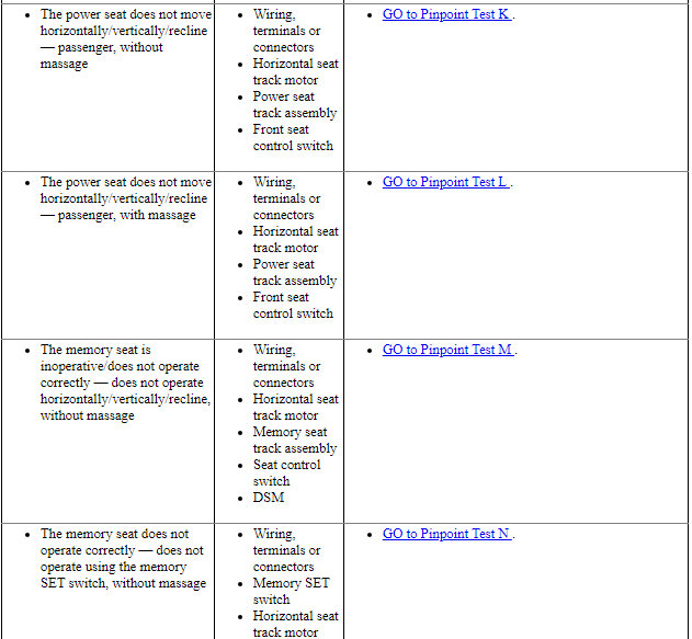
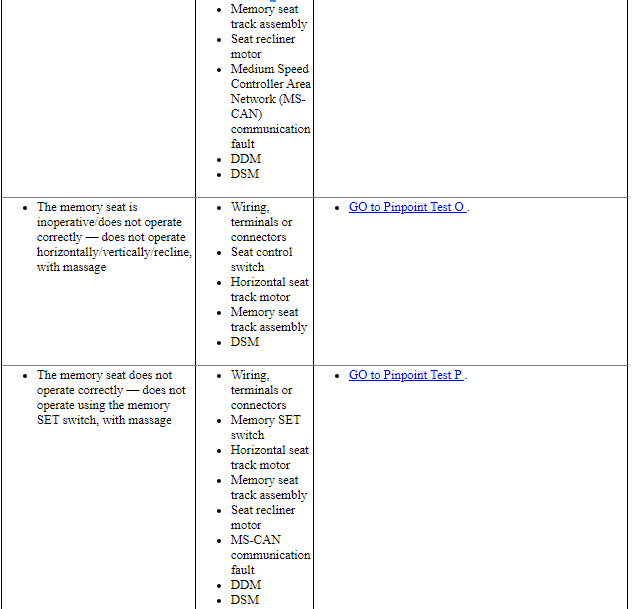
Symptom Chart

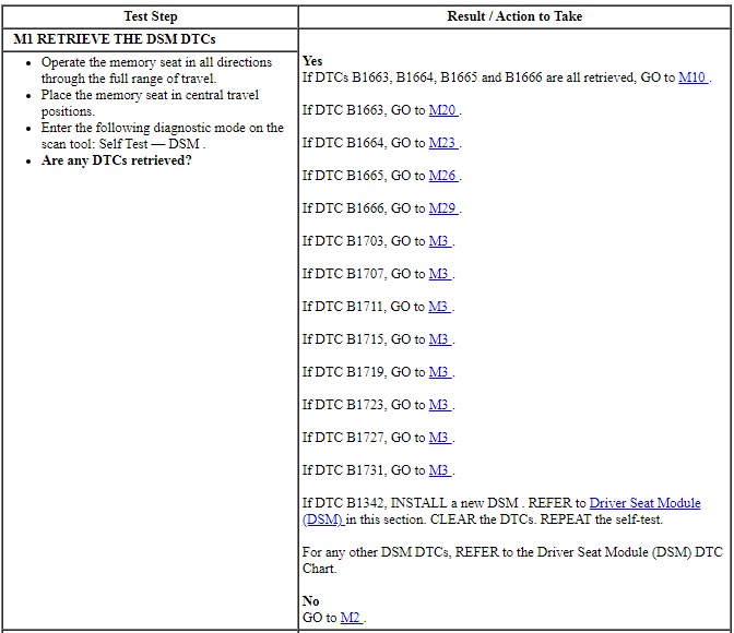
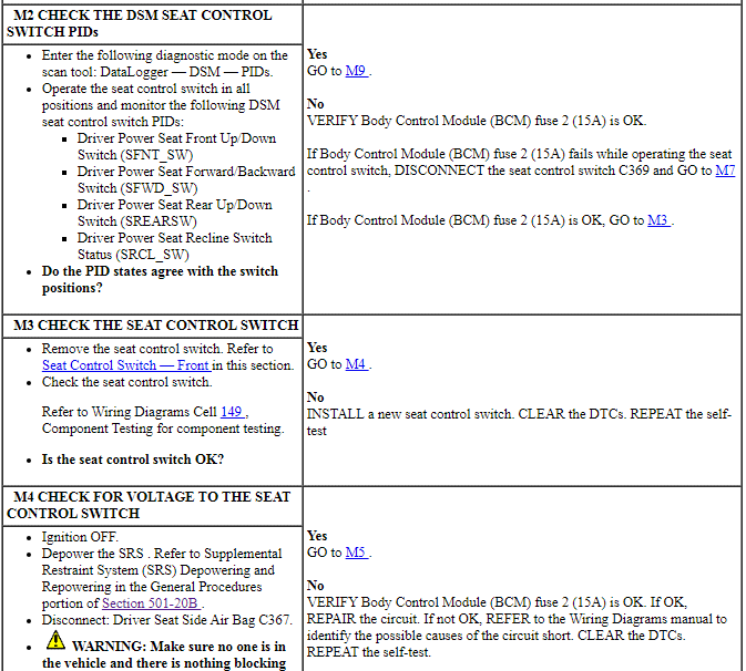
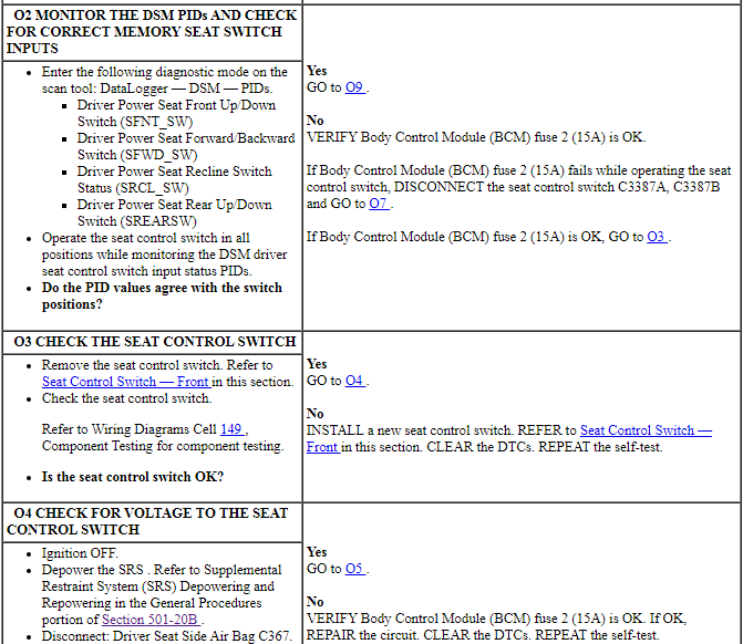
Pinpoint Tests
NOTICE: Most faults are due to connector and/or wiring concerns. Carry out a thorough inspection and verification before proceeding with the pinpoint test.
NOTICE: Use the correct probe adapter(s) from the Flex Probe Kit when taking measurements. Failure to use the correct probe adapter(s) may damage the connector.
Refer to Inspection and Verification, Driver Door Module (DDM) DTC Chart, Driver Seat Module (DSM) DTC Chart, Dual Climate Controlled Seat Module (DCSM) DTC Chart, HVAC Module DTC Chart and the Symptom Chart for direction to the appropriate pinpoint test.
Pinpoint Test A: The Power Seat is Inoperative - Driver, Without Memory
Refer to Wiring Diagrams Cell 120, Power Seats for schematic and connector information.
Normal Operation
The seat control switch supplies voltage and ground to a power seat track motor to move the seat. There are 3 power seat track motors that combine to move the seat cushion horizontally (forward/rearward) and vertically (front up/down and rear up/down).
-
This pinpoint test is intended to diagnose the following:
- Fuse
- Wiring, terminals or connectors
- Seat control switch
PINPOINT TEST A: THE POWER SEAT IS INOPERATIVE - DRIVER, WITHOUT MEMORY
NOTE: The air bag warning indicator illuminates when the correct Restraints Control Module (RCM) fuse is removed and the ignition switch is ON.
NOTE: The Supplemental Restraint System (SRS) must be fully operational and free of faults before releasing the vehicle to the customer.

Pinpoint Test D: The Power Seat is Inoperative - Passenger, Without Power Recliner
Refer to Wiring Diagrams Cell 120, Power Seats for schematic and connector information.
Normal Operation
The seat control switch supplies voltage and ground to a power seat track motor to move the seat. There are 3 power seat track motors that combine to move the seat cushion horizontally (forward/rearward) and vertically (front up/down and rear up/down).
-
This pinpoint test is intended to diagnose the following:
- Fuse
- Wiring, terminals or connectors
- Seat control switch
PINPOINT TEST D: THE POWER SEAT IS INOPERATIVE - PASSENGER, WITHOUT POWER RECLINER
NOTE: The air bag warning indicator illuminates when the correct Restraints Control Module (RCM) fuse is removed and the ignition switch is ON.
NOTE: The Supplemental Restraint System (SRS) must be fully operational and free of faults before releasing the vehicle to the customer.
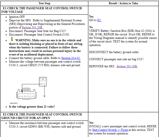
Pinpoint Test E: The Power Seat is Inoperative - Passenger, With Power Recliner, Without Massage
Refer to Wiring Diagrams Cell 120, Power Seats for schematic and connector information.
Normal Operation
The seat control switch supplies voltage and ground to a power seat track motor or power recliner motor to move the seat or backrest. There are 3 power seat track motors that combine to move the seat cushion horizontally (forward/rearward) and vertically (front up/down and rear up/down). There is an additional motor in the power recliner mechanism to move the seat backrest forward and rearward.
-
This pinpoint test is intended to diagnose the following:
- Fuse
- Wiring, terminals or connectors
- Seat control switch
PINPOINT TEST E: THE POWER SEAT IS INOPERATIVE - PASSENGER, WITH POWER RECLINER, WITHOUT MASSAGE
NOTE: The air bag warning indicator illuminates when the correct Restraints Control Module (RCM) fuse is removed and the ignition switch is ON.
NOTE: The Supplemental Restraint System (SRS) must be fully operational and free of faults before releasing the vehicle to the customer.

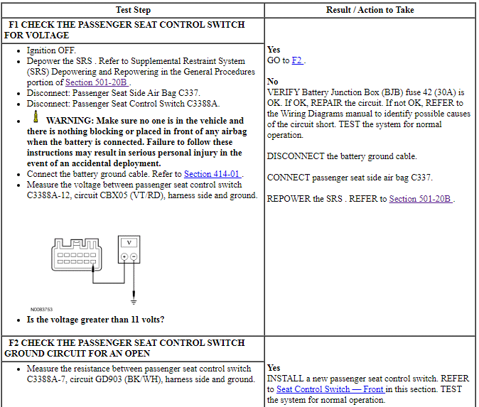
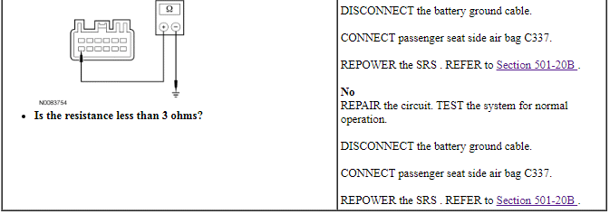
Pinpoint Test F: The Power Seat is Inoperative - Passenger, With Massage
Refer to Wiring Diagrams Cell 120, Power Seats for schematic and connector information.
Normal Operation
The seat control switch supplies voltage and ground to a power seat track motor or power recliner motor to move the seat or backrest. There are 3 power seat track motors that combine to move the seat cushion horizontally (forward/rearward) and vertically (front up/down and rear up/down). There is an additional motor in the power recliner mechanism to move the seat backrest forward and rearward.
-
This pinpoint test is intended to diagnose the following:
- Fuse
- Wiring, terminals or connectors
- Passenger seat control switch
PINPOINT TEST F: THE POWER SEAT IS INOPERATIVE - PASSENGER, WITH MASSAGE
NOTE: The air bag warning indicator illuminates when the correct Restraints Control Module (RCM) fuse is removed and the ignition is ON.
NOTE: The Supplemental Restraint System (SRS) must be fully operational and free of faults before releasing the vehicle to the customer.
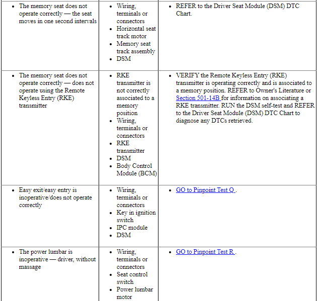
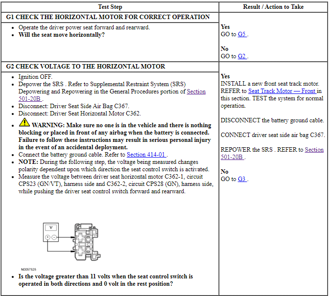
Pinpoint Test G: The Power Seat Does Not Move Horizontally/Vertically - Driver
Refer to Wiring Diagrams Cell 120, Power Seats for schematic and connector information.
Normal Operation
The seat control switch supplies voltage and ground to a power seat track motor to move the seat. There are 3 power seat track motors that combine to move the seat cushion horizontally (forward/rearward) and vertically (front up/down and rear up/down).
-
This pinpoint test is intended to diagnose the following:
- Wiring, terminals or connectors
- Seat control switch
- Horizontal seat track motor
- Power seat track assembly
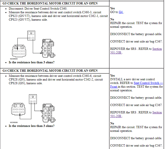
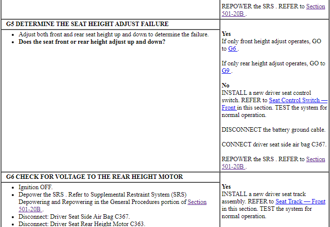
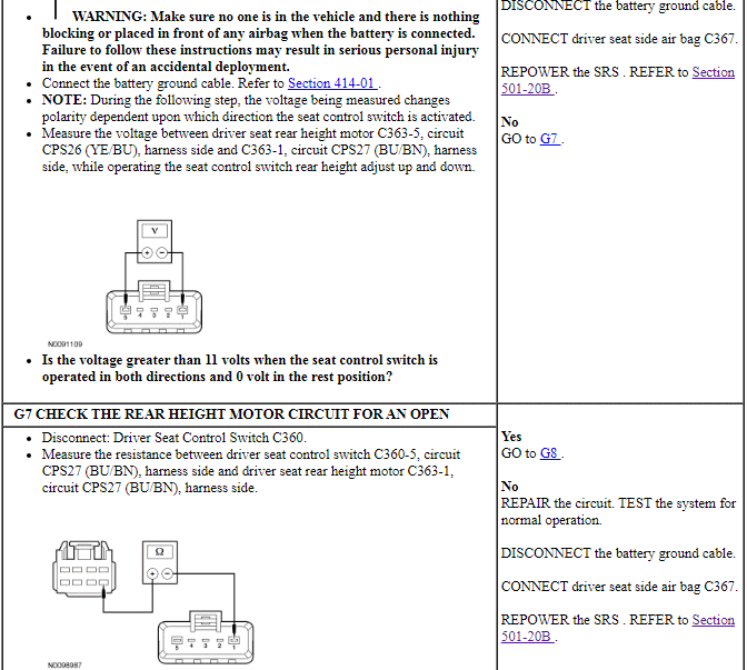
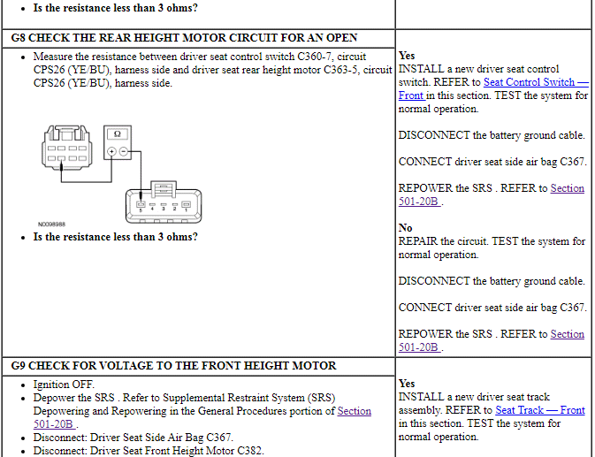
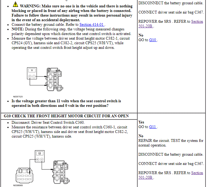
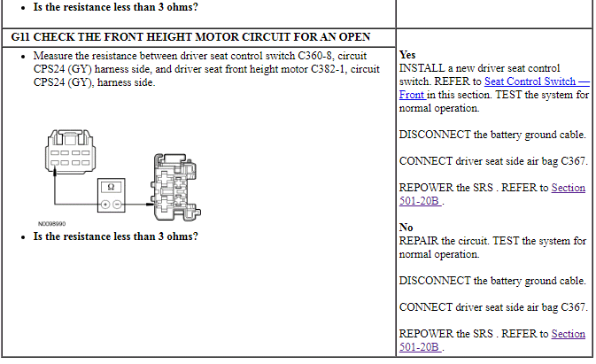
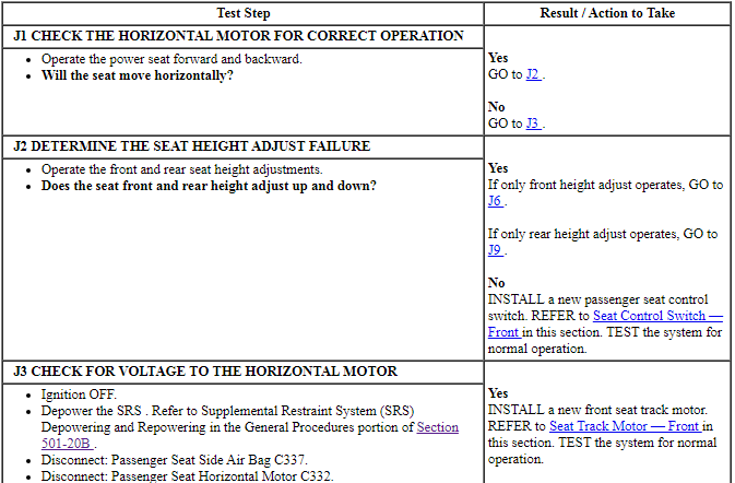
PINPOINT TEST G: THE POWER SEAT DOES NOT MOVE HORIZONTALLY/VERTICALLY - DRIVER
NOTE: The air bag warning indicator illuminates when the correct Restraints Control Module (RCM) fuse is removed and the ignition switch is ON.
NOTE: The Supplemental Restraint System (SRS) must be fully operational and free of faults before releasing the vehicle to the customer.
Pinpoint Test J: The Power Seat Does Not Move Horizontally/Vertically - Passenger, Without Power Recline
Refer to Wiring Diagrams Cell 120, Power Seats for schematic and connector information.
Normal Operation
The seat control switch supplies voltage and ground to a power seat track motor to move the seat. There are 3 power seat track motors that combine to move the seat cushion horizontally (forward/rearward) and vertically (front up/down and rear up/down).
-
This pinpoint test is intended to diagnose the following:
- Wiring, terminals or connectors
- Seat control switch
- Horizontal seat track motor
- Power seat track assembly
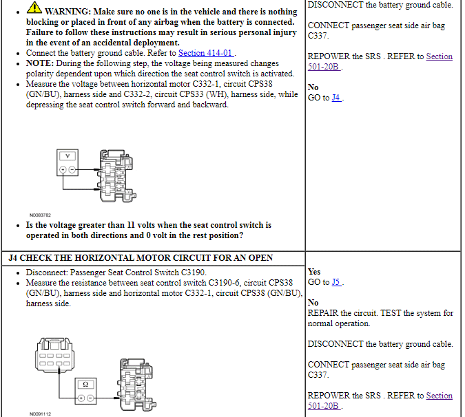
PINPOINT TEST J: THE POWER SEAT DOES NOT MOVE HORIZONTALLY/VERTICALLY - PASSENGER, WITHOUT POWER RECLINE
NOTE: The air bag warning indicator illuminates when the correct Restraints Control Module (RCM) fuse is removed and the ignition switch is ON.
NOTE: The Supplemental Restraint System (SRS) must be fully operational and free of faults before releasing the vehicle to the customer.
Pinpoint Test K: The Power Seat Does Not Move Horizontally/Vertically/Recline - Passenger, Without Massage
Refer to Wiring Diagrams Cell 120, Power Seats for schematic and connector information.
Normal Operation
The seat control switch supplies voltage and ground to a power seat track motor or power recliner motor to move the seat or backrest. There are 3 power seat track motors that combine to move the seat cushion horizontally (forward/rearward) and vertically (front up/down and rear up/down). There is an additional motor in the power recliner mechanism to move the seat backrest forward and rearward.
-
This pinpoint test is intended to diagnose the following:
- Wiring, terminals or connectors
- Seat control switch
- Horizontal seat track motor
- Power seat track assembly
- Power recliner motor
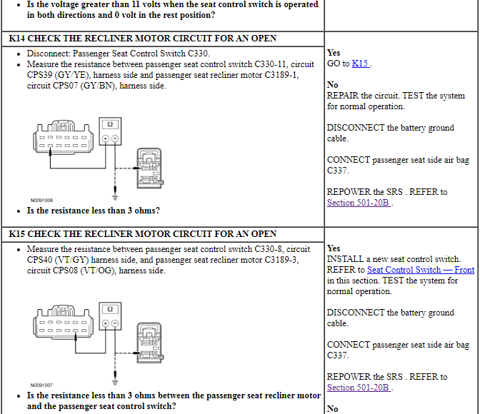
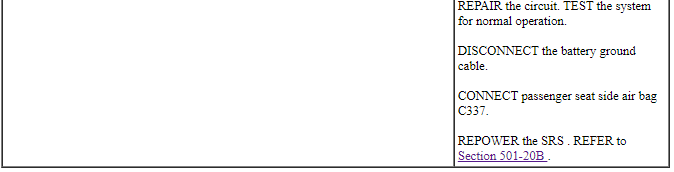
PINPOINT TEST K: THE POWER SEAT DOES NOT MOVE HORIZONTALLY/VERTICALLY/RECLINE - PASSENGER, WITHOUT MASSAGE
NOTE: The air bag warning indicator illuminates when the correct Restraints Control Module (RCM) fuse is removed and the ignition is ON.
NOTE: The Supplemental Restraint System (SRS) must be fully operational and free of faults before releasing the vehicle to the customer.

Pinpoint Test L: The Power Seat Does Not Move Horizontally/Vertically/Recline - Passenger, With Massage
Refer to Wiring Diagrams Cell 120, Power Seats for schematic and connector information.
Normal Operation
The seat control switch supplies voltage and ground to a power seat track motor or power recliner motor to move the seat or backrest. There are 3 power seat track motors that combine to move the seat cushion horizontally (forward/rearward) and vertically (front up/down and rear up/down). There is an additional motor in the power recliner mechanism to move the seat backrest forward and rearward.
-
This pinpoint test is intended to diagnose the following:
- Wiring, terminals or connectors
- Seat control switch
- Horizontal seat track motor
- Power seat track assembly
- Power recliner motor
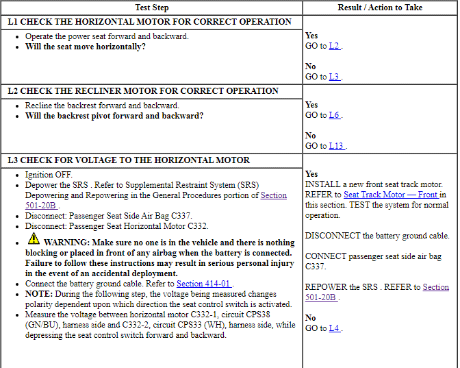
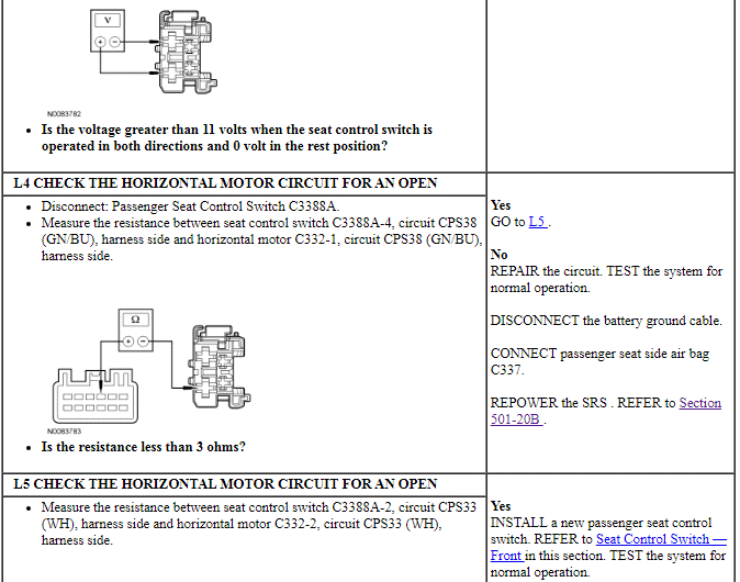
PINPOINT TEST L: THE POWER SEAT DOES NOT MOVE HORIZONTALLY/VERTICALLY/RECLINE - PASSENGER, WITH MASSAGE
NOTE: The air bag warning indicator illuminates when the correct Restraints Control Module (RCM) fuse is removed and the ignition is ON.
NOTE: The Supplemental Restraint System (SRS) must be fully operational and free of faults before releasing the vehicle to the customer.
Pinpoint Test M: The Memory Seat is Inoperative/Does Not Operate Correctly - Does Not Operate Horizontally/Vertically/Recline, Without Massage
Refer to Wiring Diagrams Cell 123, Memory Seats for schematic and connector information.
Refer to Wiring Diagrams Cell 149, Component Testing for component testing.
Normal Operation
The seat control switch supplies voltage and ground to the applicable Driver Seat Module (DSM) inputs. The DSM then supplies voltage and ground the appropriate seat track motor or seat recliner motor to move the seat in the desired direction. There are 3 seat track motors that combine to move the seat horizontally (forward/rearward) and vertically (front up/down and rear up/down). The seat recliner mechanism uses a single motor to pivot the seat backrest forward and rearward.
The following pinpoint test diagnoses a memory seat that does not operate in one or more directions when using the seat control switch. If the seat moves in all directions using the seat control switch, but does not operate using the memory SET switch, operates in short increments or does not operate at all, GO to Symptom Chart.
-
This pinpoint test is intended to diagnose the following:
- Fuse
- Wiring, terminals or connectors
- Seat control switch
- Horizontal seat track motor
- Memory seat track assembly
- Seat recliner motor
- Missing status information - Medium Speed Controller Area Network (MS-CAN) communication bus messages:
- DSM
PINPOINT TEST M: THE MEMORY SEAT IS INOPERATIVE/DOES NOT OPERATE CORRECTLY - DOES NOT OPERATE HORIZONTALLY/VERTICALLY/RECLINE, WITHOUT MASSAGE
NOTE: The air bag warning indicator illuminates when the correct Restraints Control Module (RCM) fuse is removed and the ignition is ON.
NOTE: The Supplemental Restraint System (SRS) must be fully operational and free of faults before releasing the vehicle to the customer.
NOTE: If a new DSM has been installed, all memory seat soft stops must be reset. If a new seat track or recline motor has been installed, only reset the soft stops for that component being installed new. To reset the soft stops, refer to Principles of Operation in this section.
NOTE: Refer to Description and Operation, Intelligent Access with Push Button Start in Section 419-01A to review the procedures for achieving the various ignition states (ignition OFF, ignition in ACCESSORY, ignition ON, ignition START) on vehicles with this feature.
Pinpoint Test N: The Memory Seat Does Not Operate Correctly - Does Not Operate Using the Memory SET Switch, Without Massage
Refer to Wiring Diagrams Cell 123, Memory Seats for schematic and connector information.
Normal Operation
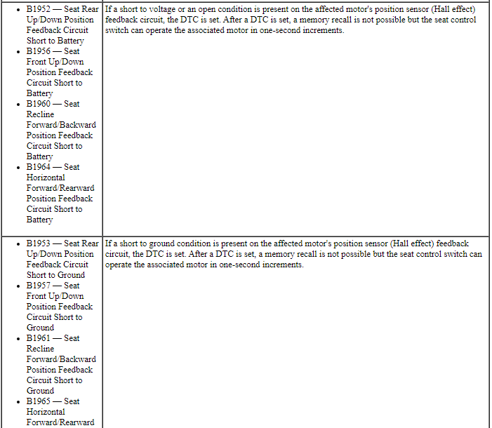
Each motor in the memory seat track and recliner mechanism contains a Hall-effect position sensor. The Driver Seat Module (DSM) supplies a voltage signal to each sensor. Each sensor sends a signal pulse back to the DSM to monitor the position of the power seat and seat backrest. The DSM stores the sensor position data when a SET command is received and uses this information to return the seat to the stored position when a recall command is received.
The memory SET switch is supplied a ground circuit. When SET button 1 or 2 is pressed, the memory SET switch supplies ground to the Driver Door Module (DDM) input circuit. The DDM communicates a memory SET command to the DSM on the Medium Speed Controller Area Network (MS-CAN). The DSM then supplies voltage and ground to the power seat track motors and power recliner motor to move the seat to the stored position. For information on programming memory positions or recalling a stored memory position, refer to Memory Position Programming in this section.
The following pinpoint test diagnoses a memory seat that does not operate correctly using the memory SET switch. If the memory seat does not move in all directions using the seat control switch, GO to Pinpoint Test M.

-
This pinpoint test is intended to diagnose the following:
- Wiring, terminals or connectors
- Memory SET switch
- Missing status information - MS-CAN communication bus messages:
- ignition key status
- gear selector position
- Horizontal seat track motor
- Memory seat track assembly
- Seat recliner motor
PINPOINT TEST N: THE MEMORY SEAT DOES NOT OPERATE CORRECTLY - DOES NOT OPERATE USING THE MEMORY SET SWITCH, WITHOUT MASSAGE
NOTE: The air bag warning indicator illuminates when the correct Restraints Control Module (RCM) fuse is removed and the ignition is ON.
NOTE: The Supplemental Restraint System (SRS) must be fully operational and free of faults before releasing the vehicle to the customer.
NOTE: If a new DSM has been installed, all memory seat soft stops must be reset. If a new seat track or recline motor has been installed, only reset the soft stops for that component being installed new. To reset the soft stops, refer to Principles of Operation in this section.
NOTE: Verify good battery condition before diagnosing the memory seat system. Poor battery condition may interfere with memory seat operation, even if vehicle starting is possible.
NOTE: Verify the PID(s) states agree with the ignition and transmission gear selector in all positions before proceeding with memory seat diagnosis.
Pinpoint Test O: The Memory Seat is Inoperative/Does Not Operate Correctly - Does Not Operate Horizontally/Vertically/Recline, With Massage
Refer to Wiring Diagrams Cell 123, Memory Seats for schematic and connector information.
Refer to Wiring Diagrams Cell 149, Component Testing for component testing.
Normal Operation
The seat control switch supplies voltage and ground to the applicable Driver Seat Module (DSM) inputs. The DSM then supplies voltage and ground to the appropriate seat track motor or seat recliner motor to move the seat in the desired direction. There are 3 seat track motors that combine to move the seat horizontally (forward/rearward) and vertically (front up/down and rear up/down). The seat recliner mechanism uses a single motor to pivot the seat backrest forward and rearward.
Each motor in the memory seat track and recliner contains a Hall-effect position sensor. The DSM supplies a shared signal feed circuit to each sensor. Each position sensor sends a signal pulse back to the DSM to monitor the position of the power seat and seat backrest. The DSM uses this information to return the seat to a stored pre-programmed position when pressing the memory SET switch or a Remote Keyless Entry (RKE). For information on programming memory positions or recalling a stored memory position, refer to Memory Position Programming in this section.
The following pinpoint test diagnoses a memory seat that does not operate in one or more directions when using the seat control switch. If the seat moves in all directions using the seat control switch, but does not operate using the memory SET switch, operates in short increments or does not operate at all, GO to Symptom Chart.
-
This pinpoint test is intended to diagnose the following:
- Fuse
- Wiring, terminals or connectors
- Seat control switch
- Missing status information (Controller Area Network (CAN) communication
bus messages):
- ignition key status
- gear selector position
- Horizontal seat track motor
- Memory seat track assembly
- Power recliner motor
- DSM
PINPOINT TEST O: THE MEMORY SEAT IS INOPERATIVE/DOES NOT OPERATE CORRECTLY - DOES NOT OPERATE HORIZONTALLY/VERTICALLY/RECLINE, WITH MASSAGE
NOTE: The air bag warning indicator illuminates when the correct Restraints Control Module (RCM) fuse is removed and the ignition is ON.
NOTE: The Supplemental Restraint System (SRS) must be fully operational and free of faults before releasing the vehicle to the customer.
NOTE: If a new DSM has been installed, all memory seat soft stops must be reset. If a new seat track or recline motor has been installed, only reset the soft stops for that component being installed new. To reset the soft stops, refer to Principles of Operation in this section.
NOTE: Verify good battery condition before diagnosing the memory seat system. Poor battery condition may interfere with memory seat operation, even if vehicle starting is possible.
NOTE: Refer to Description and Operation, Intelligent Access with Push Button Start in Section 419-01A to review the procedures for achieving the various ignition states (ignition OFF, ignition in ACCESSORY, ignition ON, ignition START) on vehicles with this feature.


Pinpoint Test P: The Memory Seat Does Not Operate Correctly - Does Not Operate Using the Memory SET Switch, With Massage
Refer to Wiring Diagrams Cell 123, Memory Seats for schematic and connector information.
Normal Operation
Each motor in the memory seat track and recliner mechanism contains a Hall-effect position sensor. The Driver Seat Module (DSM) supplies a voltage signal to each sensor. Each position sensor sends a signal pulse back to the DSM to monitor the position of the power seat and seat backrest. The DSM stores the sensor position data when a SET command is received and uses this information to return the seat to the stored position when a recall command is received.
The memory SET switch is supplied a ground circuit. When SET button 1 or 2 is pressed, the memory SET switch supplies ground to the Driver Door Module (DDM) input circuit. The DDM communicates a memory SET command to the DSM on the Medium Speed Controller Area Network (MS-CAN). The DSM then supplies voltage and ground to the power seat track motors and power recliner motor to move the seat to the stored position. For information on programming memory positions or recalling a stored memory position, refer to Memory Position Programming in this section.
The following pinpoint test diagnoses a memory seat that does not operate correctly using the memory SET switch. If the memory seat does not move in all directions using the seat control switch, GO to Pinpoint Test O.
-
This pinpoint test is intended to diagnose the following:
- Wiring, terminals or connectors
- Memory SET switch
- Missing status information (Controller Area Network (CAN) communication
bus messages):
- ignition switch status
- gear selector position
- Horizontal seat track motor
- Memory seat track assembly
- Seat recliner motor
- DDM
- DSM
PINPOINT TEST P: THE MEMORY SEAT DOES NOT OPERATE CORRECTLY - DOES NOT OPERATE USING THE MEMORY SET SWITCH, WITH MASSAGE
NOTE: The air bag warning indicator illuminates when the correct Restraints Control Module (RCM) fuse is removed and the ignition is ON.
NOTE: The Supplemental Restraint System (SRS) must be fully operational and free of faults before releasing the vehicle to the customer.
NOTE: If a new DSM has been installed, all memory seat soft stops must be reset. If a new seat track or recline motor has been installed, only reset the soft stops for that component being installed new. To reset the soft stops, refer to Principles of Operation in this section.
NOTE: Verify good battery condition before diagnosing the memory seat system. Poor battery condition may interfere with memory seat operation, even if vehicle starting is possible.
NOTE: Verify the PID(s) states agree with the ignition and transmission gear selector in all positions before proceeding with memory seat diagnosis.
Pinpoint Test Q: Easy Exit/Easy Entry is Inoperative/Does Not Operate Correctly
Normal Operation
The Driver Seat Module (DSM) receives a key out command over the Medium Speed Controller Area Network (MS-CAN) and powers the driver seat rearward about 50.8 mm (2 in) maximum.
-
This pinpoint test is intended to diagnose the following:
- Easy entry/exit feature is not enabled
- Missing status information (Controller Area Network (CAN) communication
bus messages):
- key-in-ignition status
- gear selector position
- Key-in-ignition warning switch (if equipped)
- Start/stop switch (if equipped)
- DSM
PINPOINT TEST Q: EASY EXIT/EASY ENTRY IS INOPERATIVE/DOES NOT OPERATE CORRECTLY
NOTE: Verify good battery condition before diagnosing the memory seat system. Poor battery condition may interfere with memory seat operation, even if vehicle starting is possible.
NOTE: If a new DSM has been installed, all seat soft stops must be reset. If a new seat track or recline motor has been installed, only reset the soft stops for that component being installed new. To reset the soft stops, refer to Principles of Operation in this section.
NOTE: The transmission gear selector must be in PARK and either the key removed (without Intelligent Access) or the ignition OFF (with Intelligent Access) for the easy entry/exit feature to function.
NOTE: Make sure all memory seat DTC and symptom based faults are corrected before proceeding with easy entry/exit diagnosis. Verify the PID(s) states agree with the ignition and transmission gear selector in all positions before proceeding with easy entry/exit diagnosis.
Pinpoint Test R: The Power Lumbar is Inoperative - Driver, Without Massage
Refer to Wiring Diagrams Cell 120, Power Seats for schematic and connector information.
Refer to Wiring Diagrams Cell 123, Memory Seats for schematic and connector information.
Normal Operation
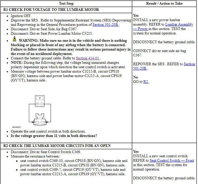
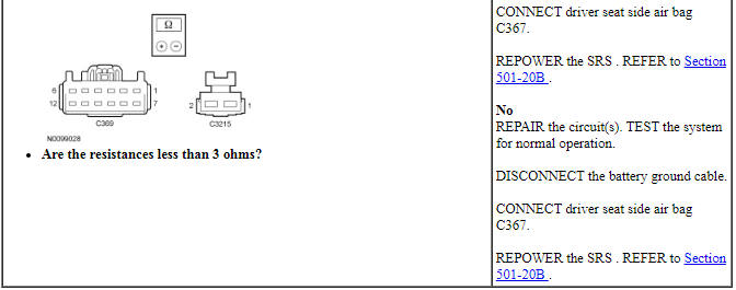
The seat control switch is supplied voltage and ground. When the lumbar button (part of seat control switch) is pressed, voltage and ground are supplied to the power lumbar motor to move the lumbar mechanism in or out.
-
This pinpoint test is intended to diagnose the following:
- Wiring, terminals or connectors
- Seat control switch
- Lumbar motor
PINPOINT TEST R: THE POWER LUMBAR IS INOPERATIVE - DRIVER, WITHOUT MASSAGE
NOTE: The air bag warning indicator illuminates when the correct Restraints Control Module (RCM) fuse is removed and the ignition switch is ON.
NOTE: The Supplemental Restraint System (SRS) must be fully operational and free of faults before releasing the vehicle to the customer.
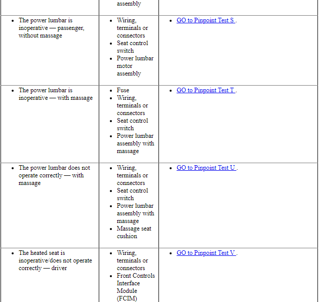
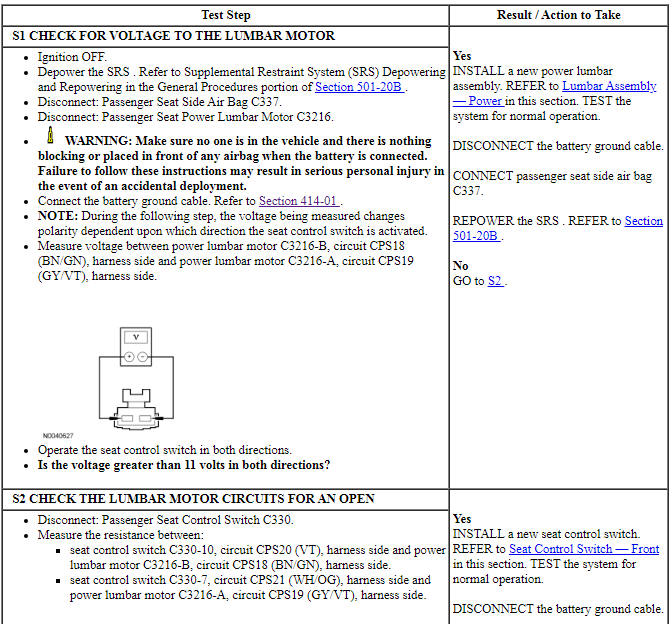
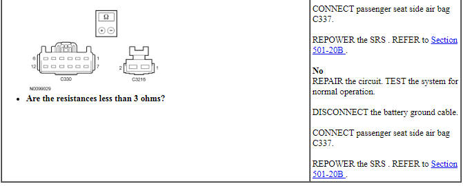
Pinpoint Test S: The Power Lumbar is Inoperative - Passenger, Without Massage
Refer to Wiring Diagrams Cell 120, Power Seats for schematic and connector information.
Normal Operation
The seat control switch is supplied battery voltage and ground. When the lumbar button (part of seat control switch) is pressed, voltage and ground are supplied to the power lumbar motor to move the lumbar mechanism in or out.
-
This pinpoint test is intended to diagnose the following:
- Wiring, terminals or connectors
- Seat control switch
- Lumbar motor
PINPOINT TEST S: THE POWER LUMBAR IS INOPERATIVE - PASSENGER, WITHOUT MASSAGE
NOTE: The air bag warning indicator illuminates when the correct Restraints Control Module (RCM) fuse is removed and the ignition switch is ON.
NOTE: The Supplemental Restraint System (SRS) must be fully operational and free of faults before releasing the vehicle to the customer.
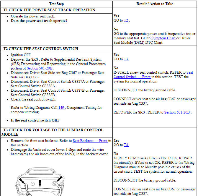
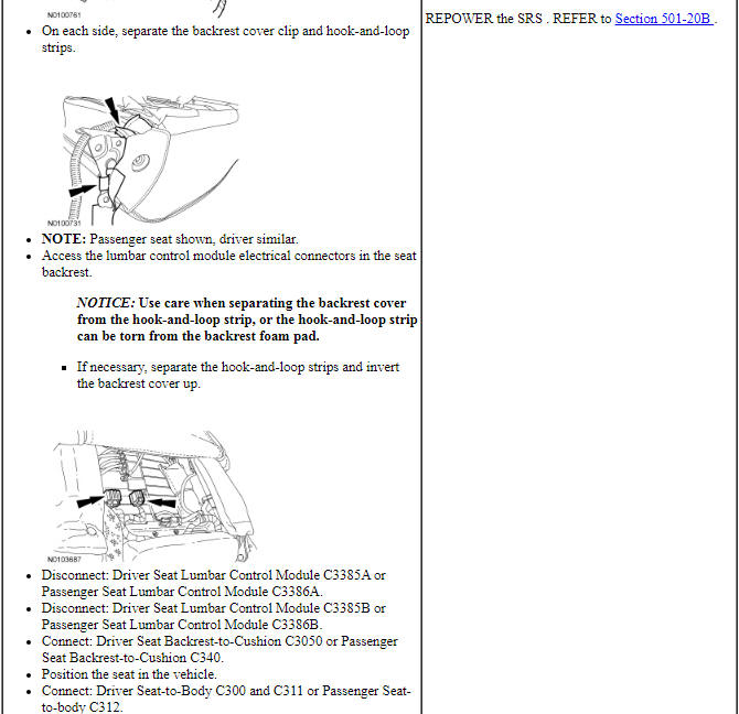
Pinpoint Test T: The Power Lumbar Is Inoperative - With Massage
Refer to Wiring Diagrams Cell 120, Power Seats for schematic and connector information.
Refer to Wiring Diagrams Cell 149, Component Testing for component testing.
Normal Operation
The lumbar control module is supplied battery voltage when the engine is running and ground. A momentary voltage signal is supplied from the seat control switch activating the lumbar control module. Voltage and ground are then supplied to the lumbar pump. Air pressure is then directed through a hose attached from the pump to the lumbar control module.
-
This pinpoint test is intended to diagnose the following:
- Fuse
- Wiring, terminals or connectors
- Seat control switch
- Power lumbar assembly with massage
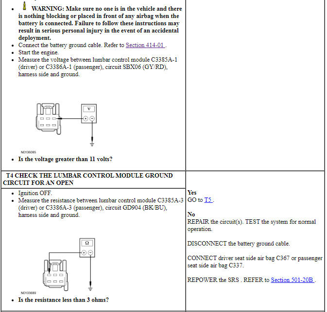
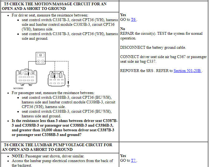
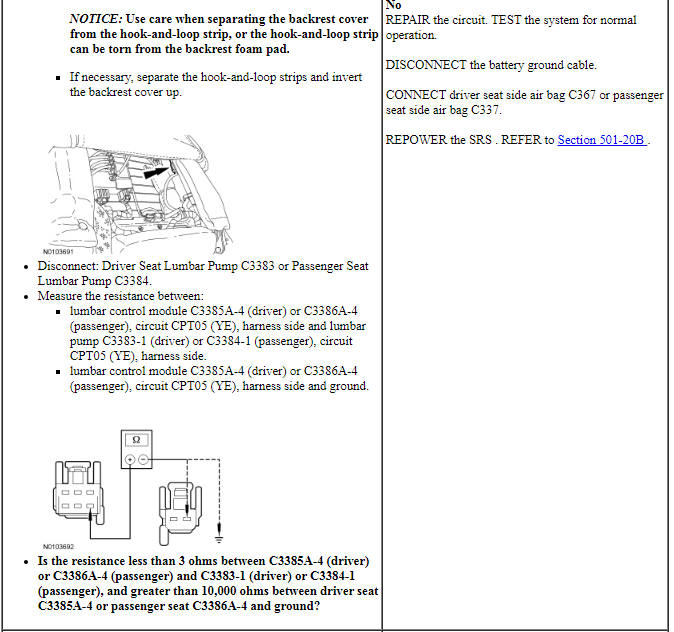
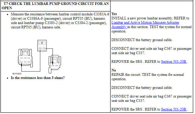
PINPOINT TEST T: THE POWER LUMBAR IS INOPERATIVE - WITH MASSAGE
NOTE: The air bag warning indicator illuminates when the correct Restraints Control Module (RCM) fuse is removed and the ignition is ON.
NOTE: The Supplemental Restraint System (SRS) must be fully operational and free of faults before releasing the vehicle to the customer.
Pinpoint Test U: The Power Lumbar Does Not Operate Correctly - With Massage
Refer to Wiring Diagrams Cell 120, Power Seats for schematic and connector information.
Refer to Wiring Diagrams Cell 149, Component Testing for component testing.
Normal Operation
The lumbar control module receives a momentary voltage signal from the seat control switch activating the lumbar control module. The module identifies the request and air pressure is then directed through hoses to the appropriate bladder from the lumbar control module.
-
This pinpoint test is intended to diagnose the following:
- Wiring, terminals or connectors
- Seat control switch
- Power lumbar assembly with massage
- Massage seat cushion
PINPOINT TEST U: THE POWER LUMBAR DOES NOT OPERATE CORRECTLY - WITH MASSAGE
NOTE: The air bag warning indicator illuminates when the correct Restraints Control Module (RCM) fuse is removed and the ignition is ON.
NOTE: The Supplemental Restraint System (SRS) must be fully operational and free of faults before releasing the vehicle to the customer.

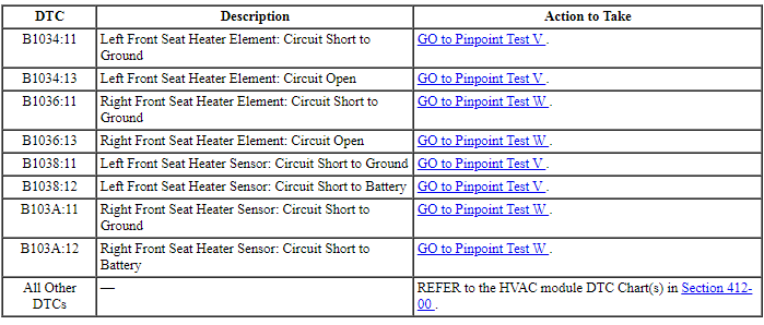
Pinpoint Test V: The Heated Seat is Inoperative/Does Not Operate Correctly - Driver
Refer to Wiring Diagrams Cell 119, Climate Controlled Seats for schematic and connector information.
Normal Operation
The engine must be running for the heated seat system to operate. The driver and passenger heated seat buttons are integral to the Front Controls Interface Module (FCIM). When a heated seat button is pressed on the FCIM, the FCIM sends the request message to the Instrument Panel Cluster (IPC) over the I-CAN. The IPC sends the message to the Body Control Module (BCM) over the High Speed Controller Area Network (HS-CAN). The message is then sent to the HVAC module over the Medium Speed Controller Area Network (MS-CAN). Upon receiving the request, the HVAC module supplies voltage to the appropriate driver and/or passenger seat cushion and backrest heater mats, which are connected in series. The driver and passenger heater mats share a common ground circuit. Temperature is maintained by the HVAC module using a sensor contained within the cushion heater mat. The HVAC module supplies a reference voltage to the temperature sensor and monitors the return signal from the temperature sensor for controlling current flow to the heater mats. The HVAC module remains on, heating the seat and maintaining temperature until commanded off from the FCIM (or until the ignition is turned OFF).
-
This pinpoint test is intended to diagnose the following:
- Wiring, terminals or connectors
- Heater mat
- FCIM
- HVAC module
PINPOINT TEST V: THE HEATED SEAT IS INOPERATIVE/DOES NOT OPERATE CORRECTLY - DRIVER
NOTE: The air bag warning indicator illuminates when the correct Restraints Control Module (RCM) fuse is removed and the ignition switch is ON.
NOTE: The Supplemental Restraint System (SRS) must be fully operational and free of faults before releasing the vehicle to the customer.

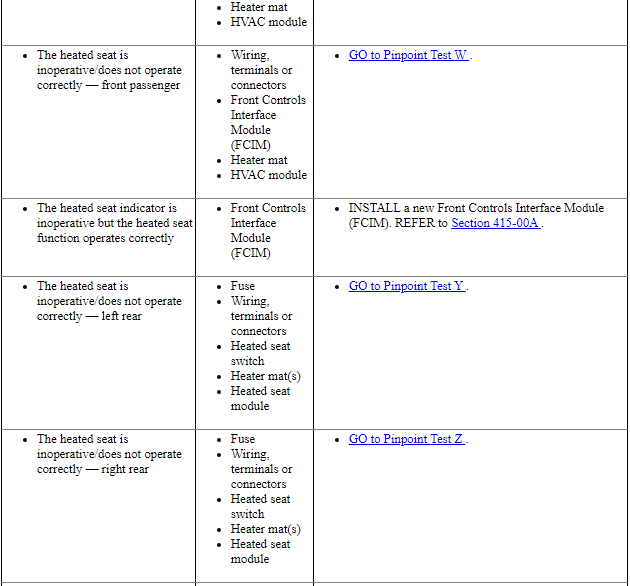
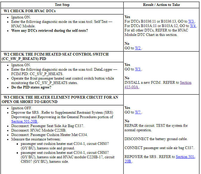
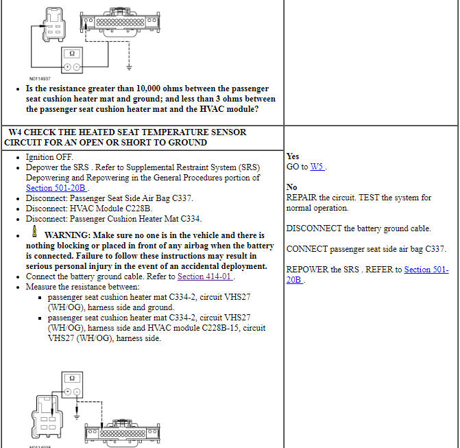
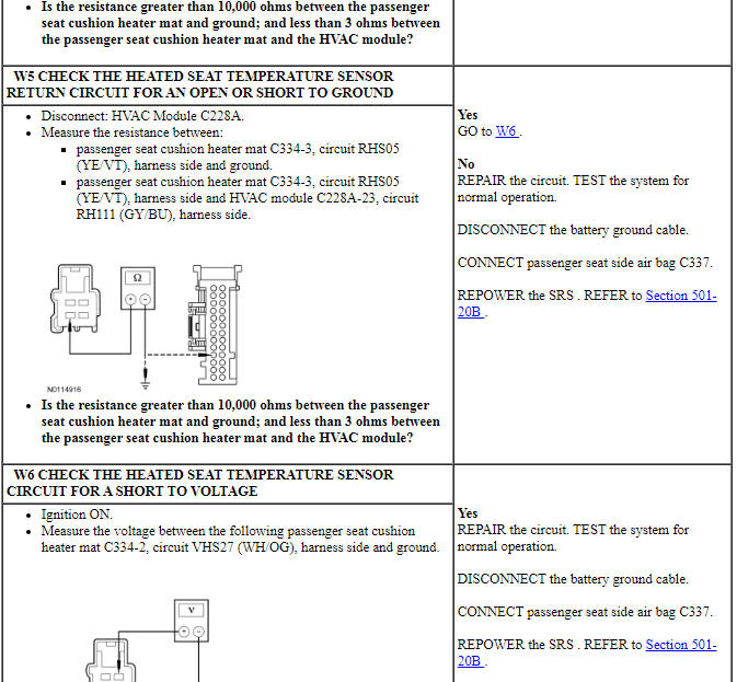
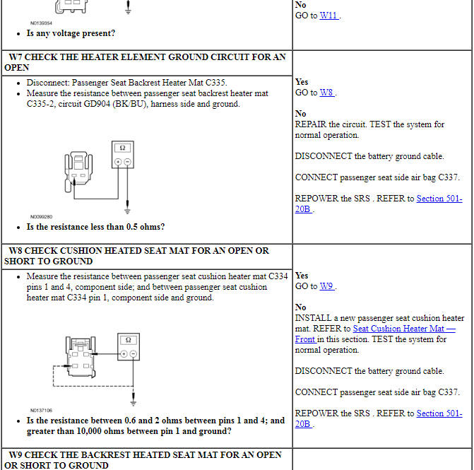
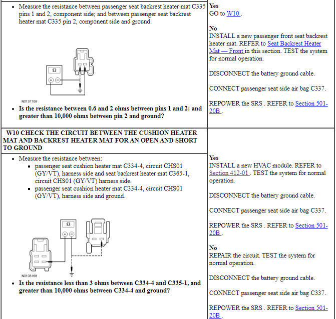
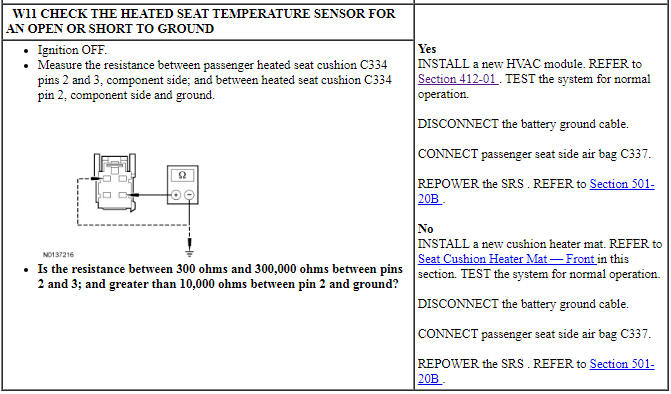
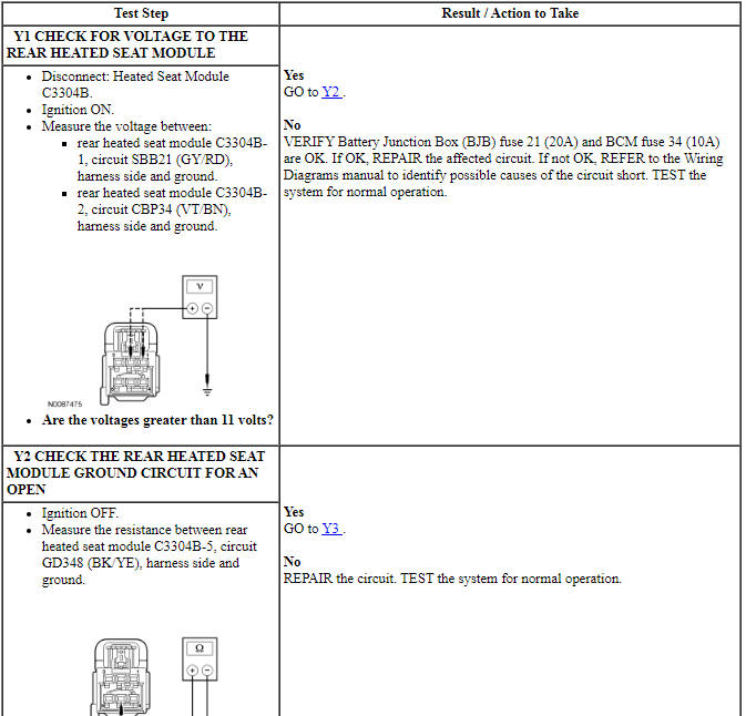
Pinpoint Test W: The Heated Seat is Inoperative/Does Not Operate Correctly- Front Passenger
Refer to Wiring Diagrams Cell 119, Climate Controlled Seats for schematic and connector information.
Normal Operation
The engine must be running for the heated seat system to operate. The driver and passenger heated seat buttons are integral to the Front Controls Interface Module (FCIM). When a heated seat button is pressed on the FCIM, the FCIM sends the request message to the Instrument Panel Cluster (IPC) over the I-CAN. The IPC sends the message to the Body Control Module (BCM) over the High Speed Controller Area Network (HS-CAN). The message is then sent to the HVAC module over the Medium Speed Controller Area Network (MS-CAN). Upon receiving the request, the HVAC module supplies voltage to the appropriate driver and/or passenger seat cushion and backrest heater mats, which are connected in series. The driver and passenger heater mats share a common ground circuit. Temperature is maintained by the HVAC module using a sensor contained within the cushion heater mat. The HVAC module supplies a reference voltage to the temperature sensor and monitors the return signal from the temperature sensor for controlling current flow to the heater mats. The HVAC module remains on, heating the seat and maintaining temperature until commanded off from the FCIM (or until the ignition is turned OFF).
-
This pinpoint test is intended to diagnose the following:
- Wiring, terminals or connectors
- Heater mat
- FCIM
- HVAC module
PINPOINT TEST W: THE HEATED SEAT IS INOPERATIVE/DOES NOT OPERATE CORRECTLY - FRONT PASSENGER
NOTE: The air bag warning indicator illuminates when the correct Restraints Control Module (RCM) fuse is removed and the ignition switch is ON.
NOTE: The Supplemental Restraint System (SRS) must be fully operational and free of faults before releasing the vehicle to the customer.
Pinpoint Test Y: The Heated Seat is Inoperative/Does Not Operate Correctly - Left Rear
Refer to Wiring Diagrams Cell 119, Climate Controlled Seats for schematic and connector information.
Normal Operation
When the LH or RH rear heated seat control switch is activated with the ignition ON, a ground signal is supplied to he heated seat module to command the system in hi heat mode or low heat mode. When commanded ON, voltage is supplied to the heated seat switch from the heated seat module to illuminate the switch indicator. The heated seat module also supplies voltage to the LH or RH rear seat cushion and backrest heater mats, which are connected in series. Temperature is maintained by the heated seat module using a sensor contained within the cushion heater mat. The heated seat module supplies a reference voltage to the temperature sensor and monitors the return signal from the temperature sensor for controlling current flow to the heater mats. The heated seat module remains ON, heating the seat and maintaining temperature until switched OFF or the ignition voltage is switched OFF.
The heated seat module faults detected will be:
- a heater feed circuit short to battery, ground or open.
- sensor circuit short to battery or open.
- heated seat switch stuck closed to ground.
-
This pinpoint test is intended to diagnose the following:
- Fuse
- Wiring, terminals or connectors
- Heater mat(s)
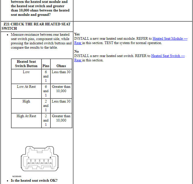
- Heated seat switch
- Heated seat module
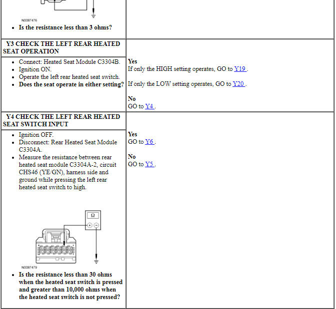
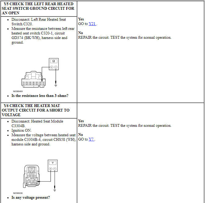
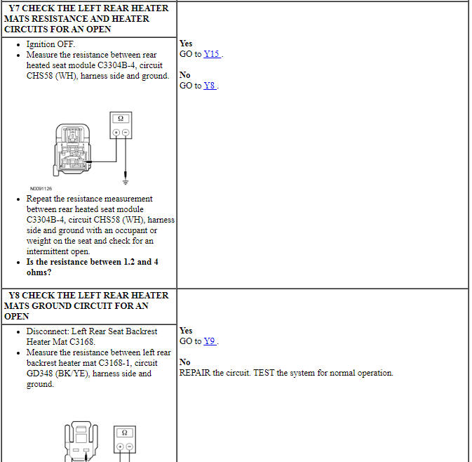
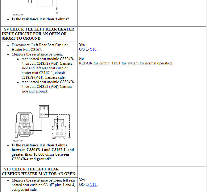
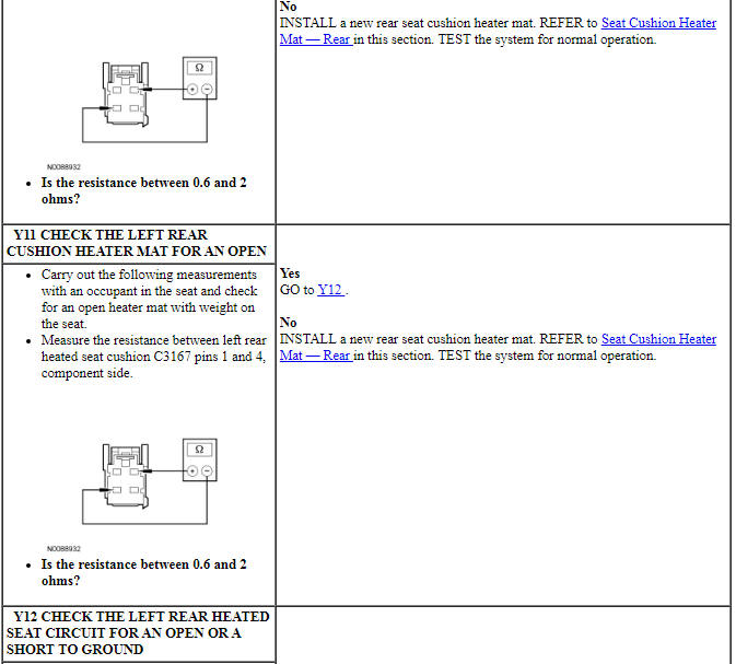
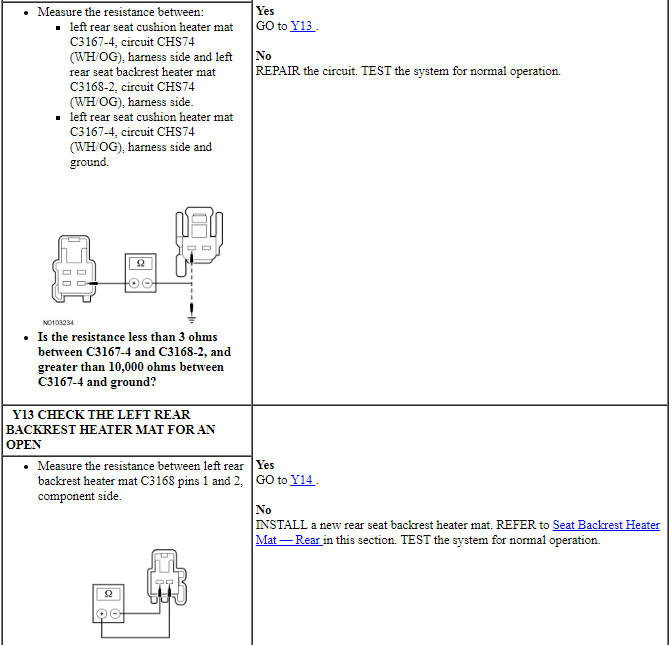
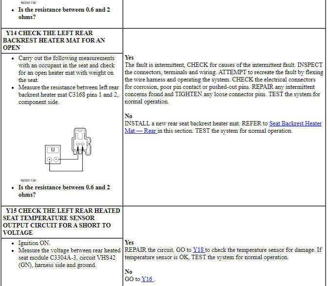
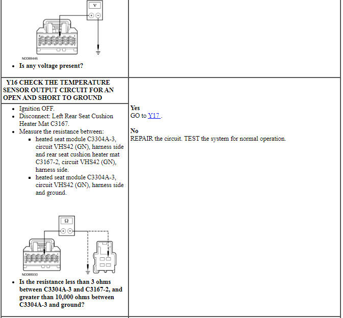
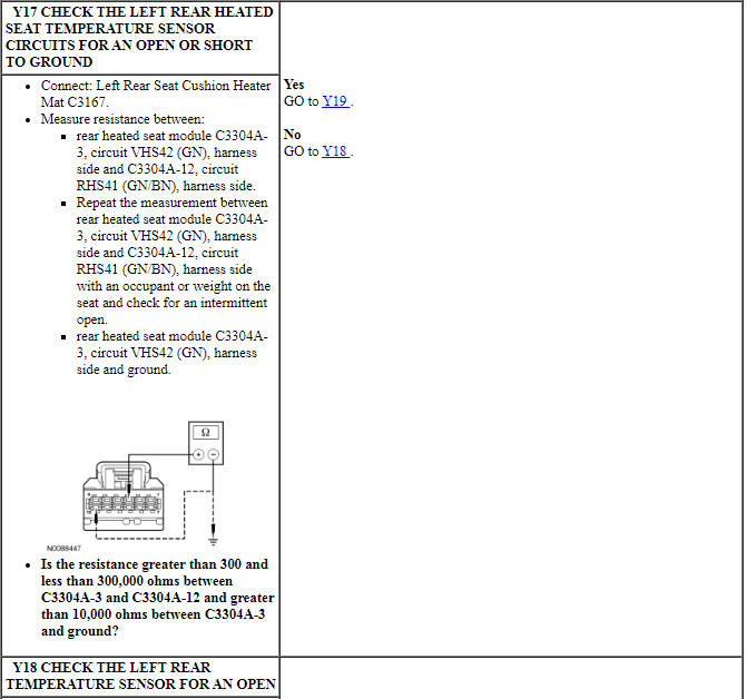
PINPOINT TEST Y: THE HEATED SEAT IS INOPERATIVE/DOES NOT OPERATE CORRECTLY - LEFT REAR
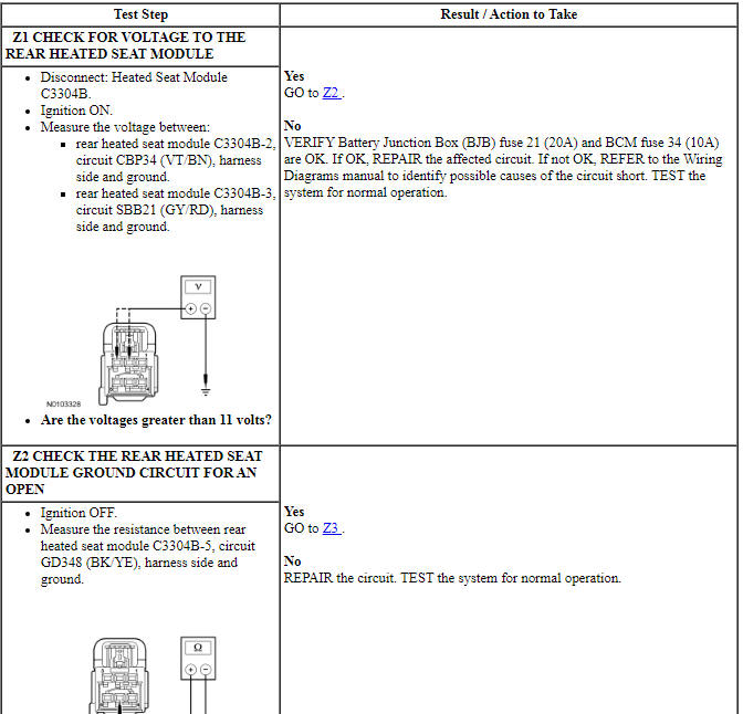
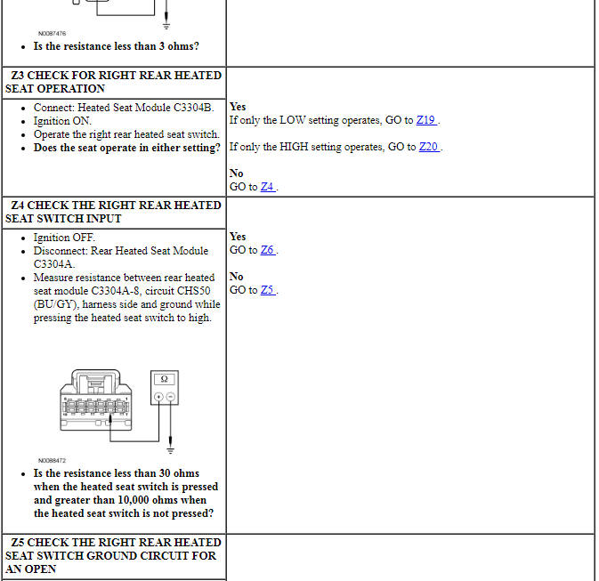
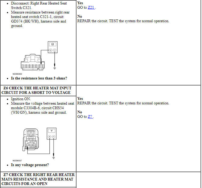
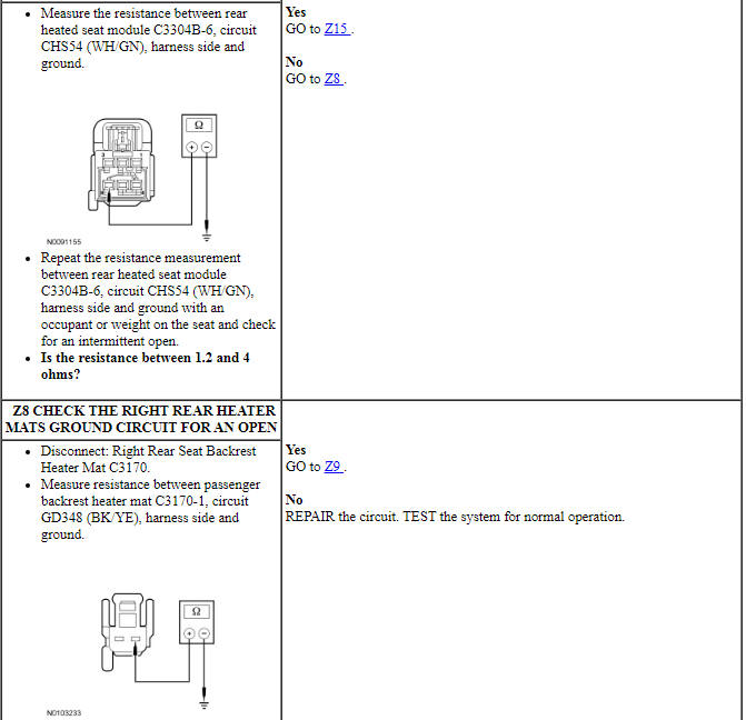
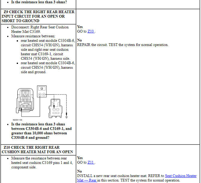
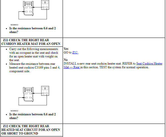
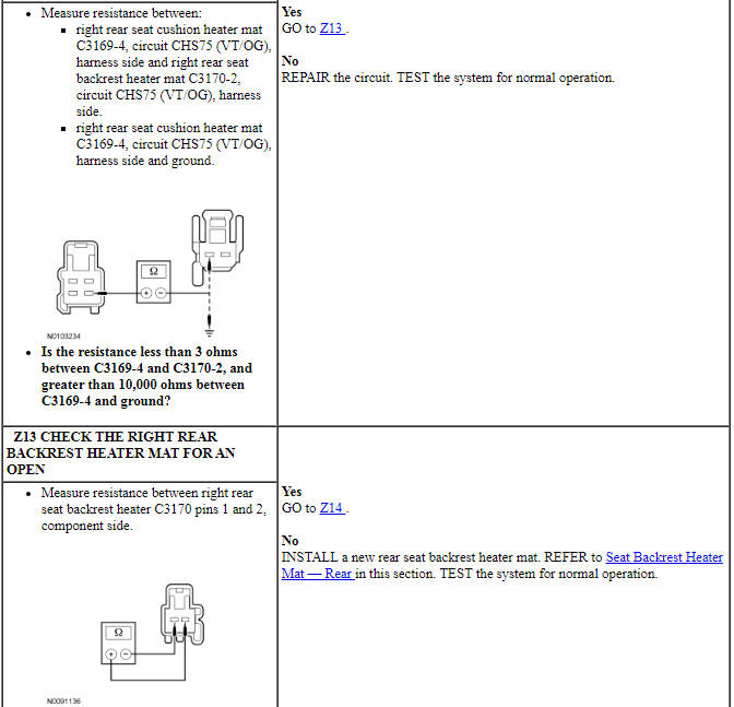
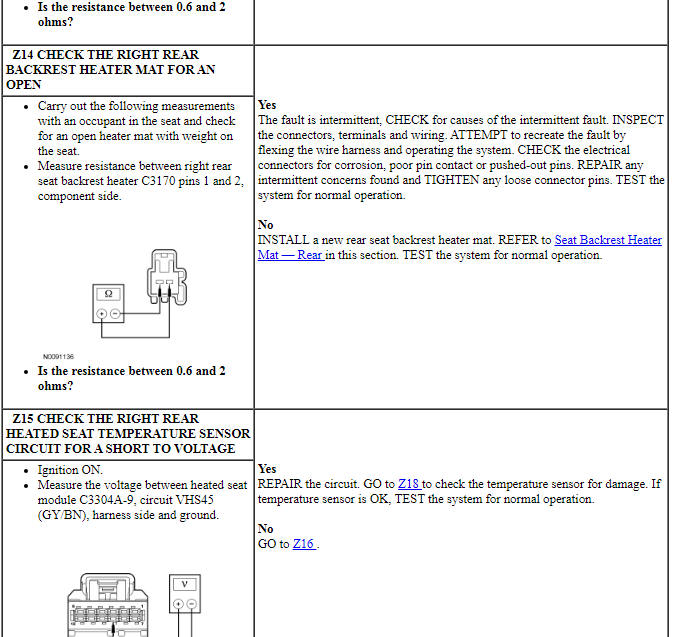
Pinpoint Test Z: The Heated Seat is Inoperative/Does Not Operate Correctly - Right Rear
Refer to Wiring Diagrams Cell 119, Climate Controlled Seats for schematic and connector information.
Normal Operation
When the LH or RH rear heated seat control switch is activated with the ignition ON, a ground signal is supplied to he heated seat module to command the system in hi heat mode or low heat mode. When commanded ON, voltage is supplied to the heated seat switch from the heated seat module to illuminate the switch indicator. The heated seat module also supplies voltage to the LH or RH rear seat cushion and backrest heater mats, which are connected in series. Temperature is maintained by the heated seat module using a sensor contained within the cushion heater mat. The heated seat module supplies a reference voltage to the temperature sensor and monitors the return signal from the temperature sensor for controlling current flow to the heater mats. The heated seat module remains ON, heating the seat and maintaining temperature until switched OFF or the ignition voltage is switched OFF.
The heated seat module faults detected will be:
- a heater feed circuit short to battery, ground or open.
- sensor circuit short to battery or open.
- heated seat switch stuck closed to ground.
-
This pinpoint test is intended to diagnose the following:
- Fuse
- Wiring, terminals or connectors
- Heater mat
- Heated seat switch
- Heated seat module
PINPOINT TEST Z: THE HEATED SEAT IS INOPERATIVE/DOES NOT OPERATE CORRECTLY - RIGHT REAR
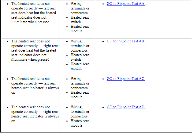
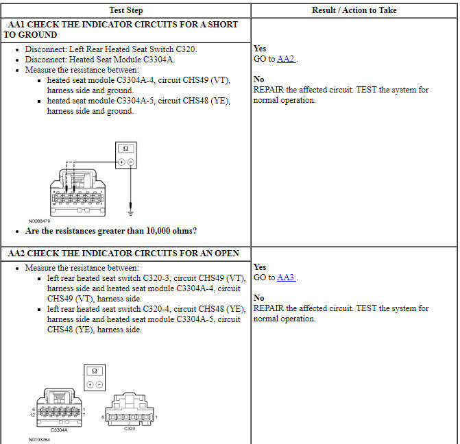
Pinpoint Test AA: The Heated Seat Does Not Operate Correctly - Left Rear Seat Does Heat But the Heated Seat Indicator Does Not Illuminate When Pressed
Refer to Wiring Diagrams Cell 119, Climate Controlled Seats for schematic and connector information.
Normal Operation
When the left rear heated seat is command on, voltage is then supplied to the left rear heated seat switch from the heated seat module to illuminate the switch indicator.
-
This pinpoint test is intended to diagnose the following:
- Wiring, terminals or connectors
- Heated seat switch
- Heated seat module
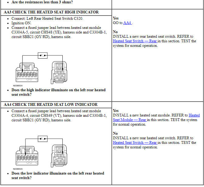
PINPOINT TEST AA: THE HEATED SEAT DOES NOT OPERATE CORRECTLY - LEFT REAR SEAT DOES HEAT BUT THE HEATED SEAT INDICATOR DOES NOT ILLUMINATE WHEN PRESSED
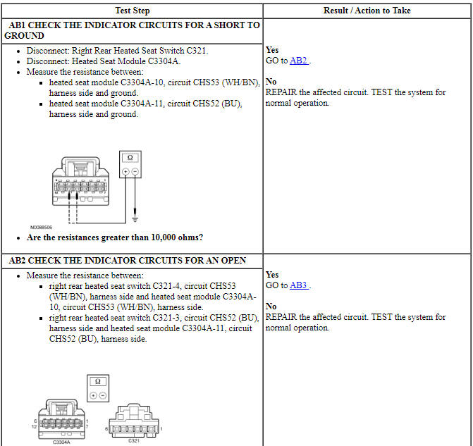
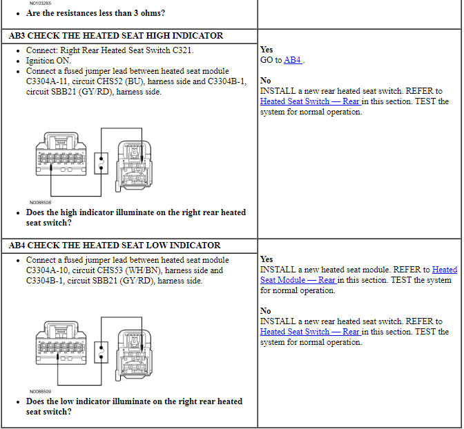
Pinpoint Test AB: The Heated Seat Does Not Operate Correctly - Right Rear Seat Does Heat But the Heated Seat Indicator Does Not Illuminate When Pressed
Refer to Wiring Diagrams Cell 119, Climate Controlled Seats for schematic and connector information.
Normal Operation
When the left rear heated seat is command on, voltage is then supplied to the left rear heated seat switch from the heated seat module to illuminate the switch indicator.
-
This pinpoint test is intended to diagnose the following:
- Wiring, terminals or connectors
- Heated seat switch
- Heated seat module
PINPOINT TEST AB: THE HEATED SEAT DOES NOT OPERATE CORRECTLY - RIGHT REAR SEAT DOES HEAT BUT THE HEATED SEAT INDICATOR DOES NOT ILLUMINATE WHEN PRESSED
Pinpoint Test AC: The Heated Seat Does Not Operate Correctly - Left Rear Heated Seat Indicator is Always On
Refer to Wiring Diagrams Cell 119, Climate Controlled Seats for schematic and connector information.
Normal Operation
Pressing the left rear heated seat switch once in either the high or low mode will activate the left rear heated seat. Voltage is then supplied from the heated seat module to the appropriate switch indicator circuit to illuminate the switch indicator. Pressing the switch button again (in the same mode) will deactivate the seat and indicator.
-
This pinpoint test is intended to diagnose the following:
- Wiring, terminals or connectors
- Heated seat module
PINPOINT TEST AC: THE HEATED SEAT DOES NOT OPERATE CORRECTLY - LEFT REAR HEATED SEAT INDICATOR IS ALWAYS ON
Pinpoint Test AD: The Heated Seat Does Not Operate Correctly - Right Rear Heated Seat Indicator is Always On
Refer to Wiring Diagrams Cell 119, Climate Controlled Seats for schematic and connector information.
Normal Operation
Pressing the left rear heated seat switch once in either the high or low mode will activate the left rear heated seat. Voltage is then supplied from the heated seat module to the appropriate switch indicator circuit to illuminate the switch indicator. Pressing the switch button again (in the same mode) will deactivate the seat and indicator.
-
This pinpoint test is intended to diagnose the following:
- Wiring, terminals or connectors
- Heated seat module
PINPOINT TEST AD: THE HEATED SEAT DOES NOT OPERATE CORRECTLY - RIGHT REAR HEATED SEAT INDICATOR IS ALWAYS ON
Pinpoint Test AF: A Single Climate Controlled Seat is Inoperative
Refer to Wiring Diagrams Cell 119, Climate Controlled Seats for schematic and connector information.
Normal Operation
The Dual Climate Controlled Seat Module (DCSM) is supplied voltage at all times, but the climate controlled seat system only operates with the engine running. The system can be operated with the ignition ON engine OFF by using a scan tool to bypass the climate controlled seat buttons on the touchscreen interface. When commanding a heat or cool mode operation in this manner, it only operates in 15 second intervals. Both voltage supply circuits are spliced together internal to the DCSM, so if one circuit becomes open, both seats can still be operated. However, if a fault occurs setting a DTC specific to either climate controlled seat, only the affected seat is disabled by the DCSM.
When the climate control seat buttons are activated on the touchscreen interface, the APIM sends the climate controlled seat commands to the Front Controls Interface Module (FCIM) using the I-CAN. The FCIM sends the request message to the IPC using the I-CAN. The IPC sends the request message to the BCM over the HS-CAN. Finally the BCM sends the communicates climate controlled seat commands to the DCSM using the MS-CAN.
-
This pinpoint test is intended to diagnose the following:
- Wiring, terminals or connectors
- Touchscreen
- DCSM
PINPOINT TEST AF: A SINGLE CLIMATE CONTROLLED SEAT IS INOPERATIVE
NOTICE: When taking measurements at Dual Climate Controlled Seat Module (DCSM) harness connectors, do not insert the electrical probes into the female connector pins. Inserting the probes into connector pins can cause intermittent or open electrical connections after reassembly resulting in Diagnostic Trouble Codes (DTCs) and system failure. Touching the tip of these connector pins is recommended instead.
Pinpoint Test AH: DTCs B103B and B1111
Refer to Wiring Diagrams Cell 119, Climate Controlled Seats for schematic and connector information.
Normal Operation
The Dual Climate Controlled Seat Module (DCSM) monitors the Thermo-Electric Device (TED) circuits. If a short to ground or voltage on any of these circuits is detected, the DTC(s) will be set.
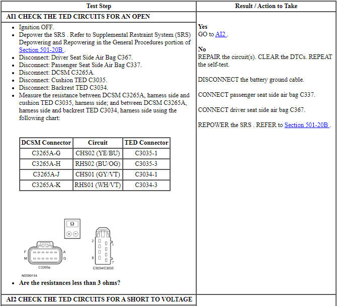
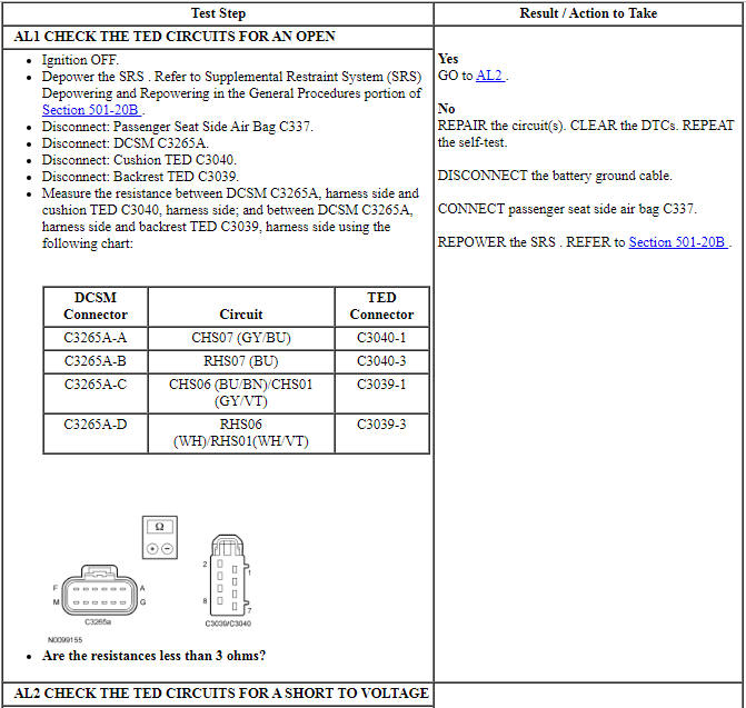
- DTC B103B (Thermo-Electric Driver Overcurrent Low) - If DCSM outputs to the driver seat backrest or cushion TED (circuit pins G, H, J or K at the DCSM connector) or any components within these circuit loops are shorted to ground or a TED resistance of less than 0.9 ohm is sensed, the DCSM will shut down the driver seat system and set this DTC.
- DTC B1111 (Driver Thermo-Electric Device Control Overtemperature Fault) - If the DCSM TED driver integrated circuit temperature exceeds 175ÂşC (347ÂşF), the DCSM will shut down the driver seat system and set this DTC.
-
This pinpoint test is intended to diagnose the following:
- Wiring, terminals or connectors
- TED assembly
- DCSM
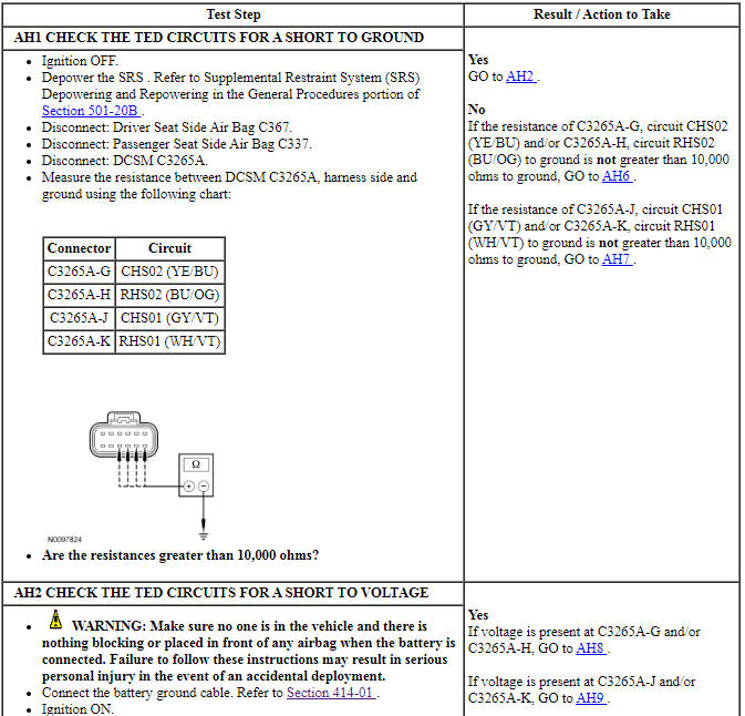
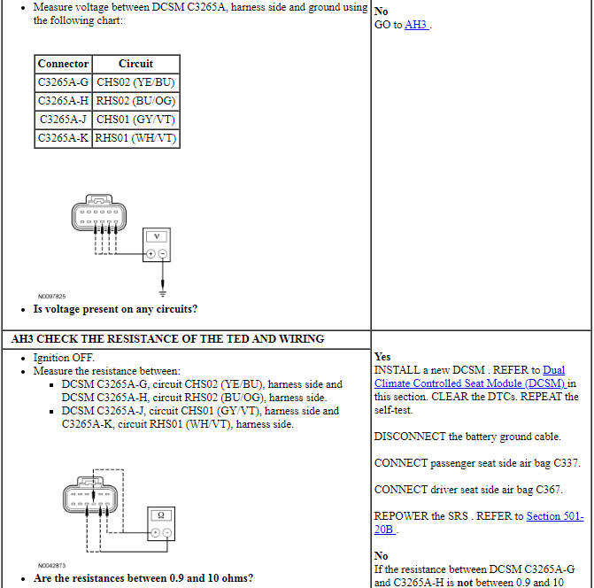
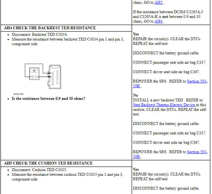
PINPOINT TEST AH: DTCs B103B AND B1111
NOTICE: When taking measurements at Dual Climate Controlled Seat Module (DCSM) harness connectors, do not insert the electrical probes into the female connector pins. Inserting the probes into connector pins can cause intermittent or open electrical connections after reassembly resulting in Diagnostic Trouble Codes (DTCs) and system failure. Touching the tip of these connector pins is recommended instead.
NOTE: The air bag warning indicator illuminates when the correct Restraints Control Module (RCM) fuse is removed and the ignition switch is ON.
NOTE: The Supplemental Restraint System (SRS) must be fully operational and free of faults before releasing the vehicle to the customer.
Pinpoint Test AI: DTC B103C
Refer to Wiring Diagrams Cell 119, Climate Controlled Seats for schematic and connector information.
Normal Operation
The Dual Climate Controlled Seat Module (DCSM) monitors the Thermo-Electric Device (TED) circuits. If an open on any of these circuits is detected, the DTC will be set.
- DTC B103C (Thermo-Electric Driver Open Load) - If the DCSM output circuits to the passenger seat backrest or cushion TED (circuit pins A, B, C or D at the DCSM connector) or any components within these circuit loops are open, disconnected or a TED resistance greater than 90,000 ohms is sensed, the DCSM continues normal operation and sets this DTC.
-
This pinpoint test is intended to diagnose the following:
- Wiring, terminals or connectors
- TED assembly
- DCSM
PINPOINT TEST AI: DTC B103C
NOTICE: When taking measurements at Dual Climate Controlled Seat Module (DCSM) harness connectors, do not insert the electrical probes into the female connector pins. Inserting the probes into connector pins can cause intermittent or open electrical connections after reassembly resulting in Diagnostic Trouble Codes (DTCs) and system failure. Touching the tip of these connector pins is recommended instead.
NOTE: The air bag warning indicator illuminates when the correct Restraints Control Module (RCM) fuse is removed and the ignition switch is ON.
NOTE: The Supplemental Restraint System (SRS) must be fully operational and free of faults before releasing the vehicle to the customer.
Pinpoint Test AJ: DTC B103D
Refer to Wiring Diagrams Cell 119, Climate Controlled Seats for schematic and connector information.
Normal Operation
The Dual Climate Controlled Seat Module (DCSM) is supplied voltage at all times, but the climate controlled seat system only operates with the engine running. The system can be operated with the ignition ON engine OFF by using a scan tool to bypass the climate controlled seat switches on the touchscreen interface. When commanding a heat or cool mode operation in this manner, the climate controlled seat system only operates in 15 second intervals. Both voltage supply circuits are spliced together internal to the DCSM, so if one circuit becomes open, both seats can still be operated. However, if a fault occurs setting a DTC specific to either climate controlled seat, only the affected seat is disabled by the DCSM.
The seat cushion is equipped with a Thermo-Electric Device (TED) assembly that includes a seat blower (fan motor, serviced as an assembly with the TED ). Similarly, the seat backrest is also equipped with its own TED assembly with blower. Cabin air is drawn through the blower and distributed to each of the TED modules located in the seat cushion and backrest. The TEDs then heat or cool the air. The air is then directed into the foam pad and manifold where it is distributed along the surface of the cushion and backrest of the seat. Once the system is activated, the DCSM uses a set of flexible algorithms to control the heating/cooling modes and the blower speed dependant on the commanded climate controlled seat settings.
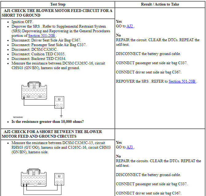
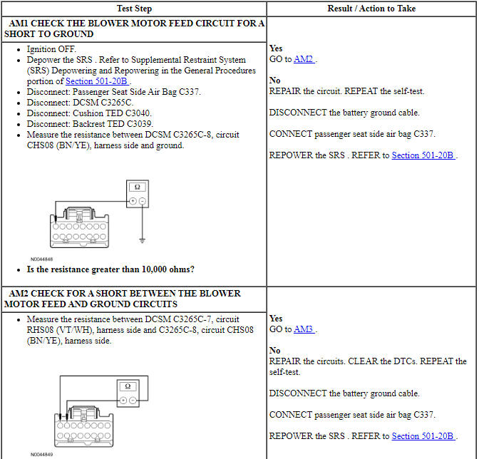
- DTC B103D (Blower Driver Overtemperature) - If the DCSM output circuits to the driver seat blower or any components within these circuit loops are shorted to ground or cause an excessive current draw, the DCSM will overheat, shut down the driver seat system and set this DTC.
-
This pinpoint test is intended to diagnose the following:
- Wiring, terminals or connectors
- Thermo-Electric Device (TED) assembly
- DCSM
PINPOINT TEST AJ: DTC B103D
NOTICE: When taking measurements at Dual Climate Controlled Seat Module (DCSM) harness connectors, do not insert the electrical probes into the female connector pins. Inserting the probes into connector pins can cause intermittent or open electrical connections after reassembly resulting in Diagnostic Trouble Codes (DTCs) and system failure. Touching the tip of these connector pins is recommended instead.
NOTE: The air bag warning indicator illuminates when the correct Restraints Control Module (RCM) fuse is removed and the ignition switch is ON.
NOTE: The Supplemental Restraint System (SRS) must be fully operational and free of faults before releasing the vehicle to the customer.
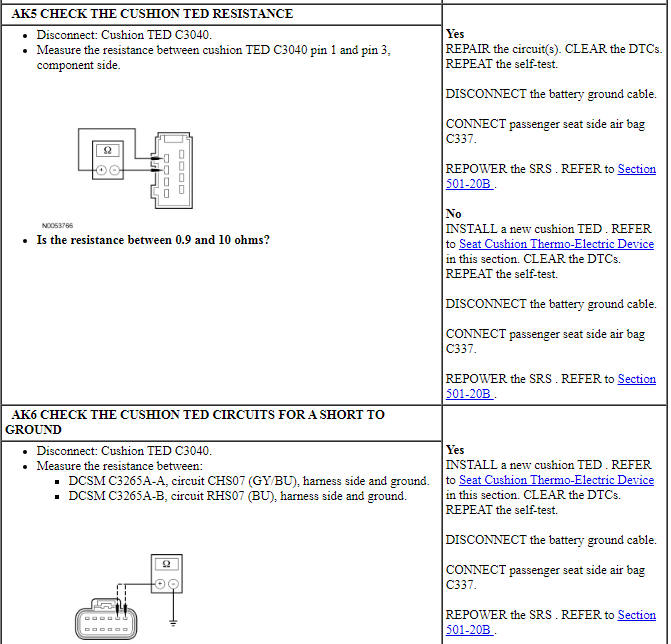
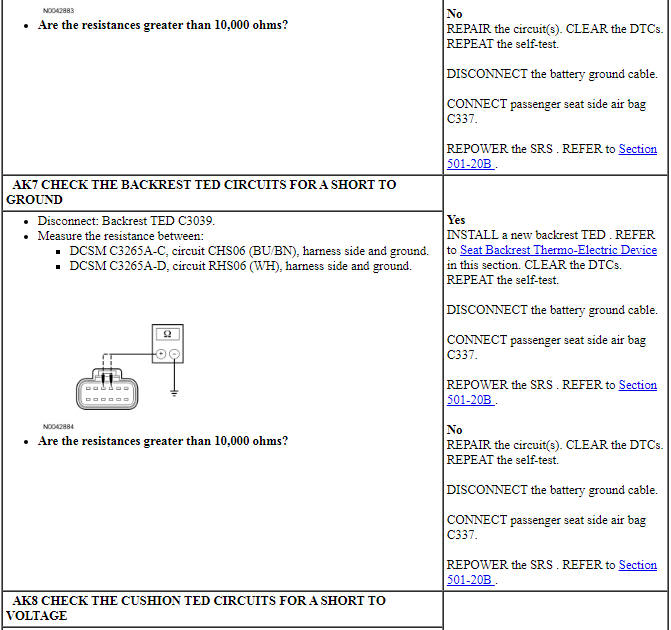
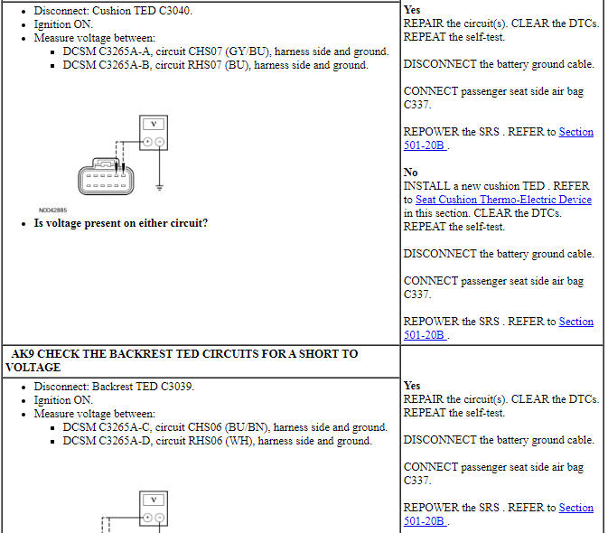
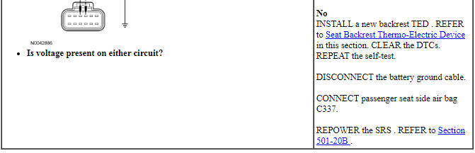
Pinpoint Test AK: DTCs B1113 and B111B
Refer to Wiring Diagrams Cell 119, Climate Controlled Seats for schematic and connector information.
Normal Operation
The seat cushion and backrest are equipped with a Thermo-Electric Device (TED) assembly that includes a seat blower (fan motor, serviced as an assembly with the TED ). When the Dual Climate Controlled Seat Module (DCSM) detects an overcurrent and/or overtemperature in the output circuits to the TEDs, it disables the affected seat and sets the following DTCs:
- DTC B1113 (Passenger Thermo-Electric Device Control Overtemperature Fault) - If the DCSM TED driver integrated circuit temperature exceeds 175ÂşC (347ÂşF), the DCSM will shut down the passenger seat system and set this DTC.
- DTC B111B (Passenger Thermo-Electric Driver Overcurrent Low) - If DCSM outputs to the passenger seat backrest or cushion TED (circuit pins A, B, C or D at the DCSM connector) or any components within these circuit loops are shorted to ground or a TED resistance of less than 0.9 ohm is sensed, the DCSM will shut down the passenger seat system and set this DTC.
-
This pinpoint test is intended to diagnose the following:
- Wiring, terminals or connectors
- TED assembly
- DCSM
PINPOINT TEST AK: DTCs B1113 AND B111B
NOTICE: When taking measurements at Dual Climate Controlled Seat Module (DCSM) harness connectors, do not insert the electrical probes into the female connector pins. Inserting the probes into connector pins can cause intermittent or open electrical connections after reassembly resulting in Diagnostic Trouble Codes (DTCs) and system failure. Touching the tip of these connector pins is recommended instead.
NOTE: The air bag warning indicator illuminates when the correct Restraints Control Module (RCM) fuse is removed and the ignition switch is ON.
NOTE: The Supplemental Restraint System (SRS) must be fully operational and free of faults before releasing the vehicle to the customer.
Pinpoint Test AL: DTC B111C
Refer to Wiring Diagrams Cell 119, Climate Controlled Seats for schematic and connector information.
Normal Operation
The seat cushion and backrest are equipped with a Thermo-Electric Device (TED) assembly that includes a seat blower (fan motor, serviced as an assembly with the TED ). If the Dual Climate Controlled Seat Module (DCSM) detects an open circuit or high TED resistance, the following DTC sets:
- DTC B111C (Passenger Thermo-Electric Driver Open Load) - If the DCSM output circuits to the passenger seat backrest or cushion TED (circuit pins A, B, C or D at the DCSM connector) or any components within these circuit loops are open, disconnected or a TED resistance greater than 90,000 ohms is sensed, the DCSM continues normal operation and sets this DTC.
-
This pinpoint test is intended to diagnose the following:
- Wiring, terminals or connectors
- TED assembly
- DCSM
PINPOINT TEST AL: DTC B111C
NOTICE: When taking measurements at Dual Climate Controlled Seat Module (DCSM) harness connectors, do not insert the electrical probes into the female connector pins. Inserting the probes into connector pins can cause intermittent or open electrical connections after reassembly resulting in Diagnostic Trouble Codes (DTCs) and system failure. Touching the tip of these connector pins is recommended instead.
NOTE: The air bag warning indicator illuminates when the correct Restraints Control Module (RCM) fuse is removed and the ignition switch is ON.
NOTE: The Supplemental Restraint System (SRS) must be fully operational and free of faults before releasing the vehicle to the customer.
Pinpoint Test AM: DTC B111D
Refer to Wiring Diagrams Cell 119, Climate Controlled Seats for schematic and connector information.
Normal Operation
The Dual Climate Controlled Seat Module (DCSM) is supplied voltage at all times, but the climate controlled seat system only operates with the engine running. The system can be operated with the ignition ON engine OFF by using a scan tool to bypass the climate controlled seat buttons on the touchscreen interface. When commanding a heat or cool mode operation in this manner, the climate controlled seat system only operates in 15 second intervals. Both voltage supply circuits are spliced together internal to the DCSM, so if one circuit becomes open, both seats can still be operated. However, if a fault occurs setting a DTC specific to either climate controlled seat, only the affected seat is disabled by the DCSM.
The seat cushion is equipped with a Thermo-Electric Device (TED) assembly that includes a seat blower (fan motor, serviced as an assembly with the TED ). Similarly, the seat backrest is also equipped with its own TED assembly with blower. Cabin air is drawn through the blower and distributed to each of the TED modules located in the seat cushion and backrest. The TEDs then heat or cool the air. The air is then directed into the foam pad and manifold where it is distributed along the surface of the cushion and backrest of the seat. Once the system is activated, the DCSM uses a set of flexible algorithms to control the heating/cooling modes and the blower speed dependant on the commanded climate controlled seat settings.
- DTC B111D (Passenger Blower Driver Overtemperature) - If the DCSM output circuits to the passenger seat blower or any components within these circuit loops are shorted to ground or cause an excessive current draw, the DCSM will overheat, shut down the passenger seat system and set this DTC.
-
This pinpoint test is intended to diagnose the following:
- Wiring, terminals or connectors
- Thermo-Electric Device (TED) assembly
- DCSM
PINPOINT TEST AM: DTC B111D
NOTICE: When taking measurements at Dual Climate Controlled Seat Module (DCSM) harness connectors, do not insert the electrical probes into the female connector pins. Inserting the probes into connector pins can cause intermittent or open electrical connections after reassembly resulting in Diagnostic Trouble Codes (DTCs) and system failure. Touching the tip of these connector pins is recommended instead.
NOTE: The air bag warning indicator illuminates when the correct Restraints Control Module (RCM) fuse is removed and the ignition switch is ON.
NOTE: The Supplemental Restraint System (SRS) must be fully operational and free of faults before releasing the vehicle to the customer.
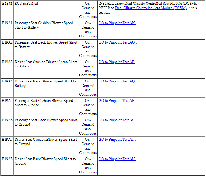
Pinpoint Test AN: DTC B19A1
Refer to Wiring Diagrams Cell 119, Climate Controlled Seats for schematic and connector information.
Normal Operation
The Dual Climate Controlled Seat Module (DCSM) supplies voltage and ground to the passenger seat cushion Thermo-Electric Device (TED). The DCSM also sends a speed control voltage signal to the TED to control blower speed.
- DTC B19A1 (Passenger Seat Cushion Blower Speed Short to Battery) - If the passenger seat cushion blower speed circuit is shorted to voltage, the DCSM will shut down the passenger seat system and set this DTC.
-
This pinpoint test is intended to diagnose the following:
- Wiring, terminals or connectors
- TED and blower assembly
- DCSM
PINPOINT TEST AN: DTC B19A1
NOTICE: When taking measurements at Dual Climate Controlled Seat Module (DCSM) harness connectors, do not insert the electrical probes into the female connector pins. Inserting the probes into connector pins can cause intermittent or open electrical connections after reassembly resulting in Diagnostic Trouble Codes (DTCs) and system failure. Touching the tip of these connector pins is recommended instead.
NOTE: The air bag warning indicator illuminates when the correct Restraints Control Module (RCM) fuse is removed and the ignition switch is ON.
NOTE: The Supplemental Restraint System (SRS) must be fully operational and free of faults before releasing the vehicle to the customer.
Pinpoint Test AO: DTC B19A2
Refer to Wiring Diagrams Cell 119, Climate Controlled Seats for schematic and connector information.
Normal Operation
The Dual Climate Controlled Seat Module (DCSM) supplies voltage and ground to the passenger seat backrest Thermo-Electric Device (TED). The DCSM also sends a speed control voltage signal to the TED to control blower speed.
- DTC B19A2 (Passenger Seat Back Blower Speed Short to Battery) - If the passenger seat backrest blower speed circuit is shorted to voltage, the DCSM will shut down the passenger seat system and set this DTC.
-
This pinpoint test is intended to diagnose the following:
- Wiring, terminals or connectors
- TED and blower assembly
- DCSM
PINPOINT TEST AO: DTC B19A2
NOTICE: When taking measurements at Dual Climate Controlled Seat Module (DCSM) harness connectors, do not insert the electrical probes into the female connector pins. Inserting the probes into connector pins can cause intermittent or open electrical connections after reassembly resulting in Diagnostic Trouble Codes (DTCs) and system failure. Touching the tip of these connector pins is recommended instead.
NOTE: The air bag warning indicator illuminates when the correct Restraints Control Module (RCM) fuse is removed and the ignition switch is ON.
NOTE: The Supplemental Restraint System (SRS) must be fully operational and free of faults before releasing the vehicle to the customer.
Pinpoint Test AP: DTC B19A3
Refer to Wiring Diagrams Cell 119, Climate Controlled Seats for schematic and connector information.
Normal Operation
The Dual Climate Controlled Seat Module (DCSM) supplies voltage and ground to the driver seat cushion Thermo-Electric Device (TED). The DCSM also sends a speed control voltage signal to the TED to control blower speed.
- DTC B19A3 (Driver Seat Cushion Blower Speed Short to Battery) - If the driver seat cushion blower speed circuit is shorted to voltage, the DCSM will shut down the driver seat system and set this DTC.
-
This pinpoint test is intended to diagnose the following:
- Wiring, terminals or connectors
- TED and blower assembly
- DCSM
PINPOINT TEST AP: DTC B19A3
NOTICE: When taking measurements at Dual Climate Controlled Seat Module (DCSM) harness connectors, do not insert the electrical probes into the female connector pins. Inserting the probes into connector pins can cause intermittent or open electrical connections after reassembly resulting in Diagnostic Trouble Codes (DTCs) and system failure. Touching the tip of these connector pins is recommended instead.
NOTE: The air bag warning indicator illuminates when the correct Restraints Control Module (RCM) fuse is removed and the ignition switch is ON.
NOTE: The Supplemental Restraint System (SRS) must be fully operational and free of faults before releasing the vehicle to the customer.
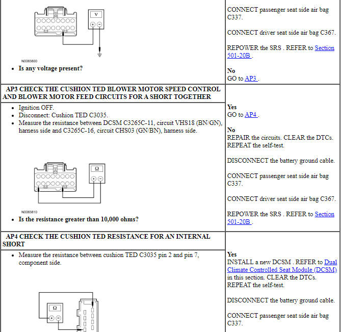
Pinpoint Test AQ: DTC B19A4
Refer to Wiring Diagrams Cell 119, Climate Controlled Seats for schematic and connector information.
Normal Operation
The Dual Climate Controlled Seat Module (DCSM) supplies voltage and ground to the driver seat backrest Thermo-Electric Device (TED). The DCSM also sends a speed control voltage signal to the TED to control blower speed.
- DTC B19A4 (Driver Seat Back Blower Speed Short to Battery) - If the driver seat backrest blower speed circuit is shorted to voltage, the DCSM will shut down the driver seat system and set this DTC.
-
This pinpoint test is intended to diagnose the following:
- Wiring, terminals or connectors
- TED and blower assembly
- DCSM
PINPOINT TEST AQ: DTC B19A4
NOTICE: When taking measurements at Dual Climate Controlled Seat Module (DCSM) harness connectors, do not insert the electrical probes into the female connector pins. Inserting the probes into connector pins can cause intermittent or open electrical connections after reassembly resulting in Diagnostic Trouble Codes (DTCs) and system failure. Touching the tip of these connector pins is recommended instead.
NOTE: The air bag warning indicator illuminates when the correct Restraints Control Module (RCM) fuse is removed and the ignition switch is ON.
NOTE: The Supplemental Restraint System (SRS) must be fully operational and free of faults before releasing the vehicle to the customer.
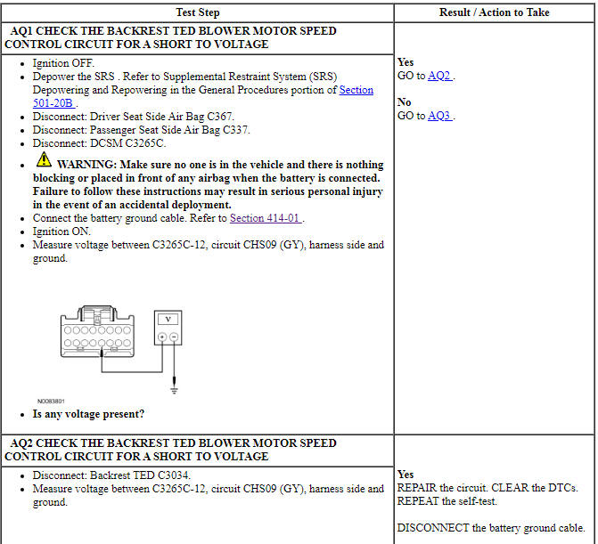
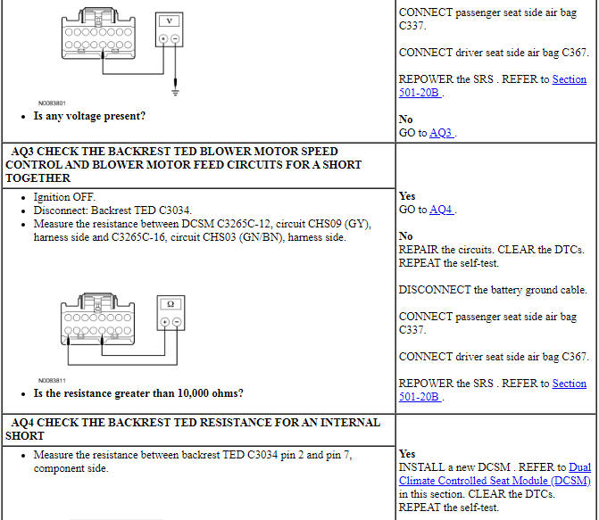
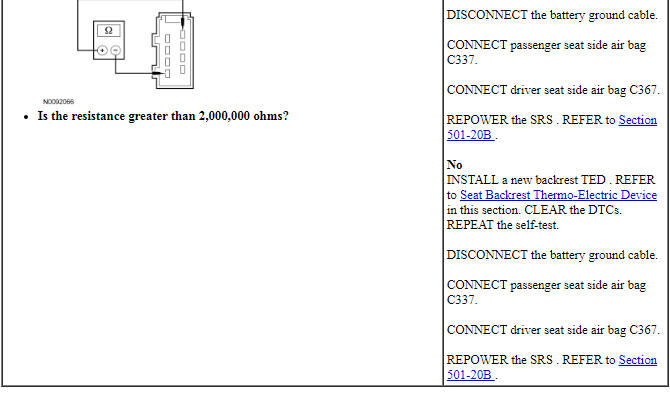
Pinpoint Test AR: DTC B19A5
Refer to Wiring Diagrams Cell 119, Climate Controlled Seats for schematic and connector information.
Normal Operation
The Dual Climate Controlled Seat Module (DCSM) supplies voltage and ground to the passenger seat cushion Thermo-Electric Device (TED). The DCSM also sends a speed control voltage signal to the TED to control blower speed.
- DTC B19A5 (Passenger Seat Cushion Blower Speed Short to Ground) - If the passenger seat cushion blower speed circuit is shorted to ground, the DCSM will shut down the passenger seat system and set this DTC.
-
This pinpoint test is intended to diagnose the following:
- Wiring, terminals or connectors
- TED and blower assembly
- DCSM
PINPOINT TEST AR: DTC B19A5
NOTICE: When taking measurements at Dual Climate Controlled Seat Module (DCSM) harness connectors, do not insert the electrical probes into the female connector pins. Inserting the probes into connector pins can cause intermittent or open electrical connections after reassembly resulting in Diagnostic Trouble Codes (DTCs) and system failure. Touching the tip of these connector pins is recommended instead.
NOTE: The air bag warning indicator illuminates when the correct Restraints Control Module (RCM) fuse is removed and the ignition switch is ON.
NOTE: The Supplemental Restraint System (SRS) must be fully operational and free of faults before releasing the vehicle to the customer.
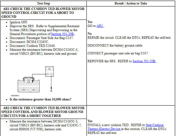
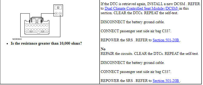
Pinpoint Test AS: DTC B19A6
Refer to Wiring Diagrams Cell 119, Climate Controlled Seats for schematic and connector information.
Normal Operation
The Dual Climate Controlled Seat Module (DCSM) supplies voltage and ground to the passenger seat backrest Thermo-Electric Device (TED). The DCSM also sends a speed control voltage signal to the TED to control blower speed.
- DTC B19A6 (Passenger Seat Back Blower Speed Short to Ground) - If the passenger seat backrest blower speed circuit is shorted to ground, the DCSM will shut down the passenger seat system and set this DTC.
-
This pinpoint test is intended to diagnose the following:
- Wiring, terminals or connectors
- TED and blower assembly
- DCSM
PINPOINT TEST AS: DTC B19A6
NOTICE: When taking measurements at Dual Climate Controlled Seat Module (DCSM) harness connectors, do not insert the electrical probes into the female connector pins. Inserting the probes into connector pins can cause intermittent or open electrical connections after reassembly resulting in Diagnostic Trouble Codes (DTCs) and system failure. Touching the tip of these connector pins is recommended instead.
NOTE: The air bag warning indicator illuminates when the correct Restraints Control Module (RCM) fuse is removed and the ignition switch is ON.
NOTE: The Supplemental Restraint System (SRS) must be fully operational and free of faults before releasing the vehicle to the customer.
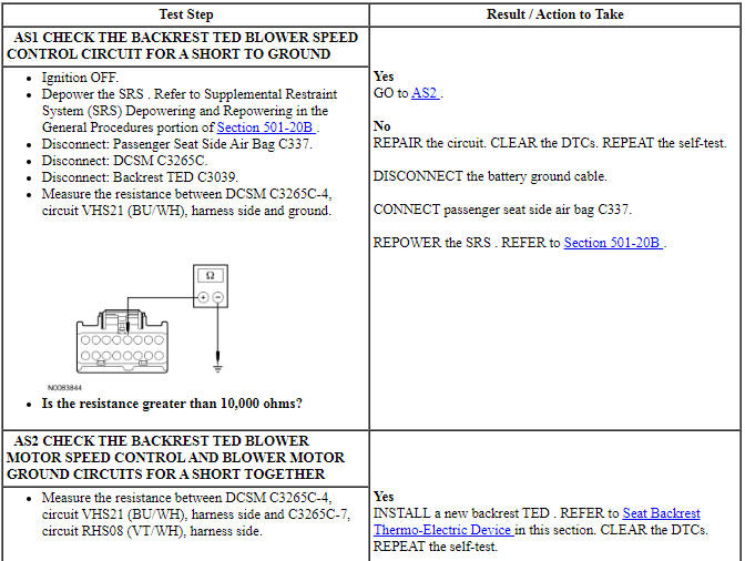

Pinpoint Test AT: DTC B19A7
Refer to Wiring Diagrams Cell 119, Climate Controlled Seats for schematic and connector information.
Normal Operation
The Dual Climate Controlled Seat Module (DCSM) supplies voltage and ground to the driver seat cushion Thermo-Electric Device (TED). The DCSM also sends a speed control voltage signal to the TED to control blower speed.
- DTC B19A7 (Driver Seat Cushion Blower Speed Short to Ground) - If the driver seat cushion blower speed circuit is shorted to ground, the DCSM will shut down the driver seat system and set this DTC.
-
This pinpoint test is intended to diagnose the following:
- Wiring, terminals or connectors
- TED and blower assembly
- DCSM
PINPOINT TEST AT: DTC B19A7
NOTICE: When taking measurements at Dual Climate Controlled Seat Module (DCSM) harness connectors, do not insert the electrical probes into the female connector pins. Inserting the probes into connector pins can cause intermittent or open electrical connections after reassembly resulting in Diagnostic Trouble Codes (DTCs) and system failure. Touching the tip of these connector pins is recommended instead.
NOTE: The air bag warning indicator illuminates when the correct Restraints Control Module (RCM) fuse is removed and the ignition switch is ON.
NOTE: The Supplemental Restraint System (SRS) must be fully operational and free of faults before releasing the vehicle to the customer.
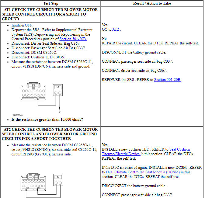
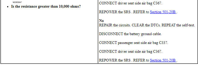
Pinpoint Test AU: DTC B19A8
Refer to Wiring Diagrams Cell 119, Climate Controlled Seats for schematic and connector information.
Normal Operation
The Dual Climate Controlled Seat Module (DCSM) supplies voltage and ground to the driver seat backrest Thermo-Electric Device (TED). The DCSM also sends a speed control voltage signal to the TED to control blower speed.
- DTC B19A8 (Driver Seat Back Blower Speed Short to Ground) - If the driver seat backrest blower speed circuit is shorted to ground, the DCSM will shut down the driver seat system and set this DTC.
-
This pinpoint test is intended to diagnose the following:
- Wiring, terminals or connectors
- TED and blower assembly
- DCSM
PINPOINT TEST AU: DTC B19A8
NOTICE: When taking measurements at Dual Climate Controlled Seat Module (DCSM) harness connectors, do not insert the electrical probes into the female connector pins. Inserting the probes into connector pins can cause intermittent or open electrical connections after reassembly resulting in Diagnostic Trouble Codes (DTCs) and system failure. Touching the tip of these connector pins is recommended instead.
NOTE: The air bag warning indicator illuminates when the correct Restraints Control Module (RCM) fuse is removed and the ignition switch is ON.
NOTE: The Supplemental Restraint System (SRS) must be fully operational and free of faults before releasing the vehicle to the customer.
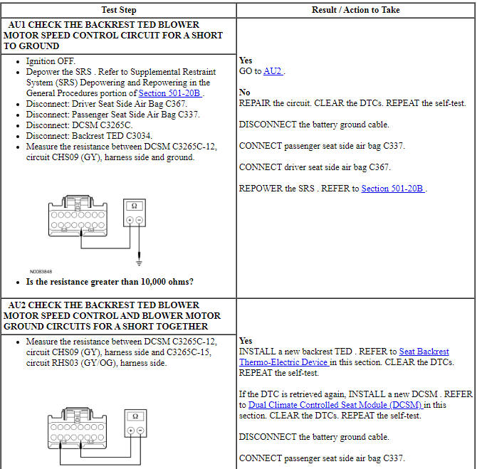
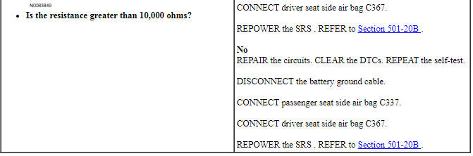
Pinpoint Test AV: DTC B2486
Refer to Wiring Diagrams Cell 123, Memory Seats for schematic and connector information.
Refer to Wiring Diagrams Cell 119, Climate Controlled Seats for schematic and connector information.
Normal Operation
The Dual Climate Controlled Seat Module (DCSM) monitors the input voltage for correct operation. If the DCSM detects input voltage below 11 volts or above 15 volts, it will store DTC B2486 in memory. If DTC B2486 is set, the DCSM enters a standby mode and suspends the system outputs for both seat's operation until system voltage between 10 and 15 volts is restored and a climate controlled seat switch button is selected on.
- DTC B2486 (Climate Control Seat Module Voltage Out of Range) - If the DCSM detects voltage below 11 volts or greater than 15 volts, the DTC is set.
-
This pinpoint test is intended to diagnose the following:
- Wiring, terminals or connectors
- DCSM
PINPOINT TEST AV: DTC B2486
NOTICE: When taking measurements at Dual Climate Controlled Seat Module (DCSM) harness connectors, do not insert the electrical probes into the female connector pins. Inserting the probes into connector pins can cause intermittent or open electrical connections after reassembly resulting in Diagnostic Trouble Codes (DTCs) and system failure. Touching the tip of these connector pins is recommended instead.
NOTE: DTCs B2486 or B1676 can be set if the vehicle has been recently jump started, the battery has been recently charged or the battery has been discharged. The battery may become discharged due to excessive load(s) on the charging system from aftermarket accessories or if the battery has been left unattended with the accessories on.
NOTE: The air bag warning indicator illuminates when the correct Restraints Control Module (RCM) fuse is removed and the ignition switch is ON.
NOTE: The Supplemental Restraint System (SRS) must be fully operational and free of faults before releasing the vehicle to the customer.
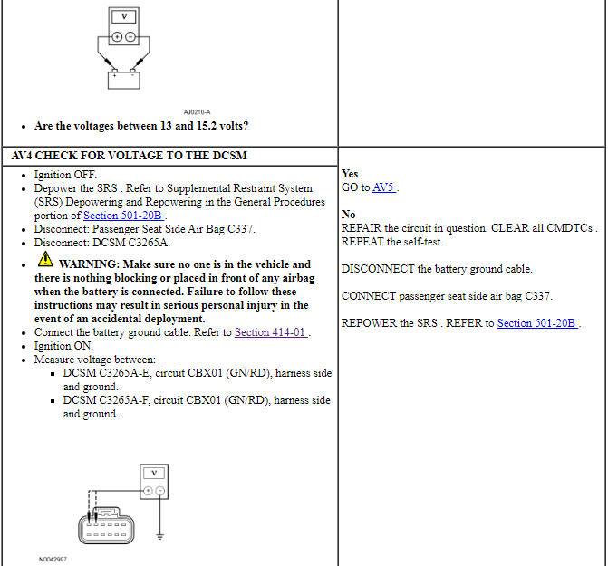
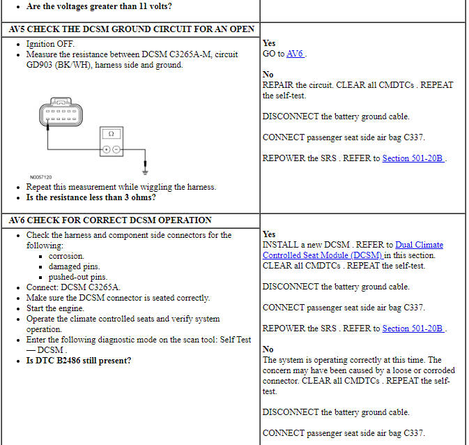

Pinpoint Test AW: DTC B2729
Refer to Wiring Diagrams Cell 119, Climate Controlled Seats for schematic and connector information.
Normal Operation
The Dual Climate Controlled Seat Module (DCSM) monitors seat cushion temperature while it supplies voltage and ground to both blower motors. The DCSM also supplies a variable voltage signal to control the blower speed. Cabin air enters the blower through a filter attached to the Thermo-Electric Device (TED) housing. Heated or cooled air exits the TED and flows through a manifold attached to the foam pad.
- DTC B2729 (Cushion Over-Temp Detected) - If the driver seat cushion TED temperature exceeds 70ÂşC (158ÂşF) in cool mode or 85ÂşC (185ÂşF) in heat mode for more than 34 seconds the DCSM shuts down the driver seat system and sets this DTC.
-
This pinpoint test is intended to diagnose the following:
- Wiring, terminals or connectors
- Restricted cushion TED filter
- Crushed or restricted cushion foam pad
- Crushed or restricted climate controlled seat manifold
- Cushion TED assembly
- Dual Climate Controlled Seat Module (DCSM)
PINPOINT TEST AW: DTC B2729
NOTICE: When taking measurements at Dual Climate Controlled Seat Module (DCSM) harness connectors, do not insert the electrical probes into the female connector pins. Inserting the probes into connector pins can cause intermittent or open electrical connections after reassembly resulting in Diagnostic Trouble Codes (DTCs) and system failure. Touching the tip of these connector pins is recommended instead.
NOTE: The air bag warning indicator illuminates when the correct Restraints Control Module (RCM) fuse is removed and the ignition is ON.
NOTE: The Supplemental Restraint System (SRS) must be fully operational and free of faults before releasing the vehicle to the customer.
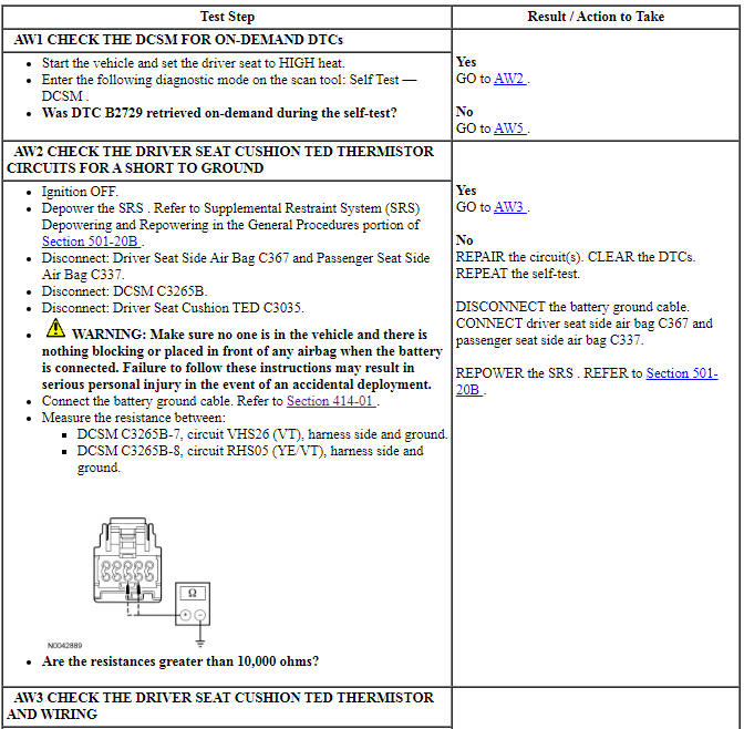
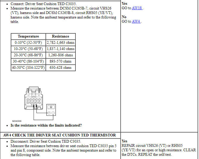
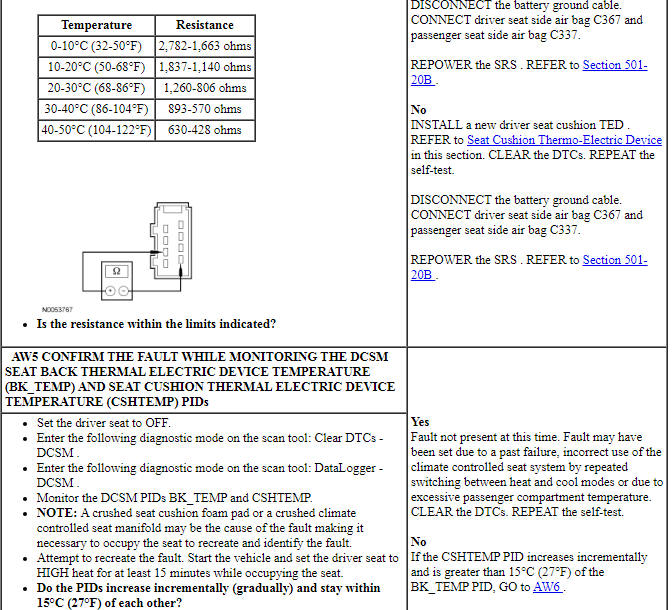
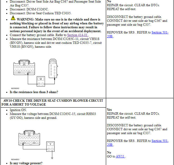
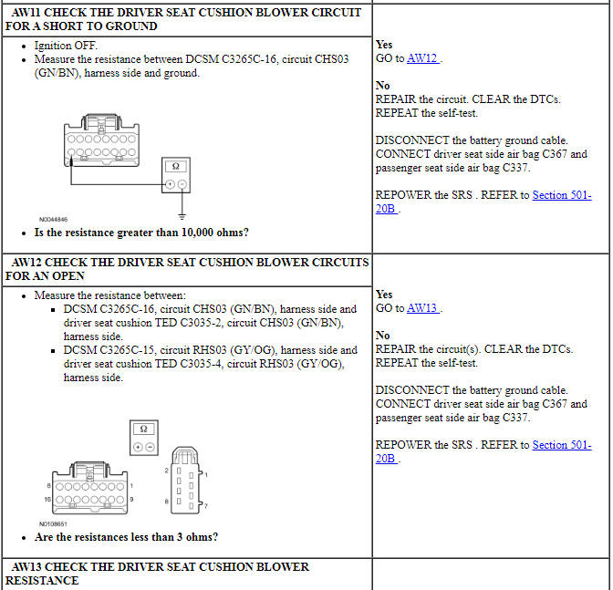
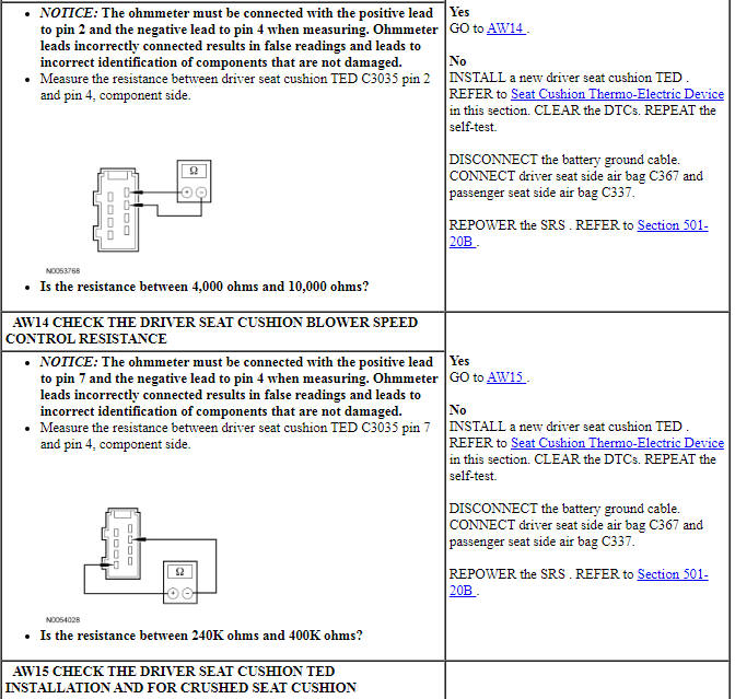
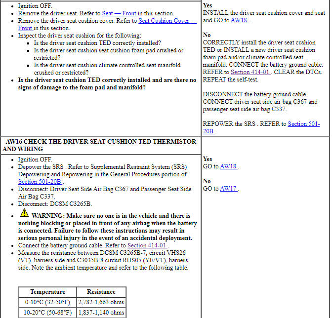
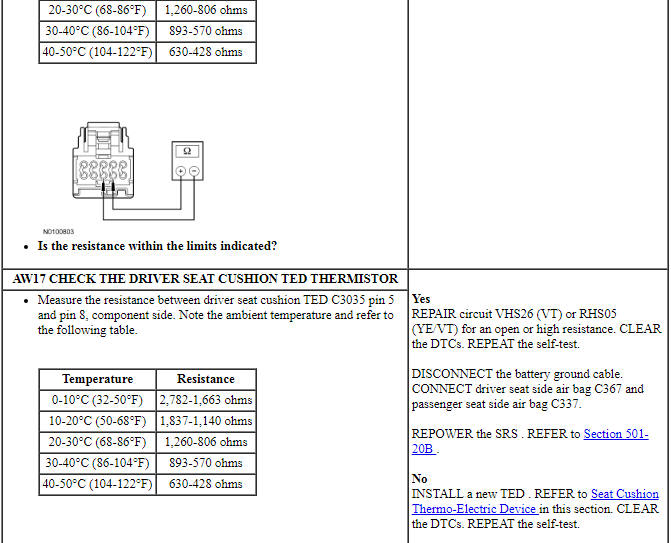
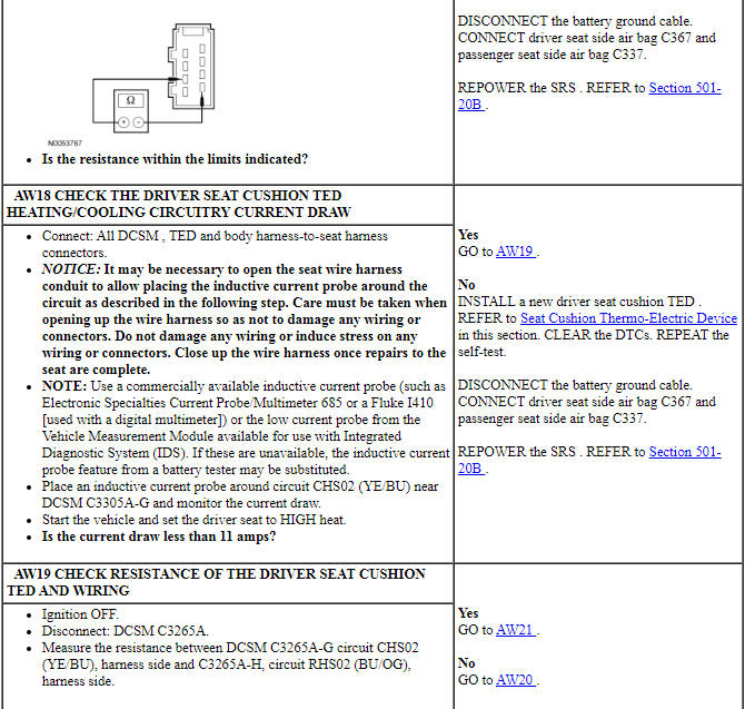
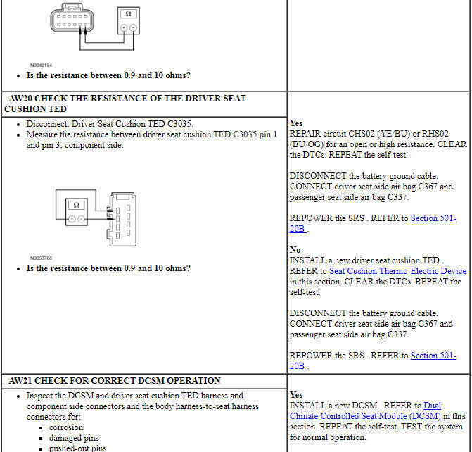
Pinpoint Test AX: DTC B272A
Refer to Wiring Diagrams Cell 119, Climate Controlled Seats for schematic and connector information.
Normal Operation
The Dual Climate Controlled Seat Module (DCSM) monitors seat cushion temperature while it supplies voltage and ground to both blower motors. The DCSM also supplies a variable voltage signal to control the blower speed. Cabin air enters the blower through a filter attached to the Thermo-Electric Device (TED) housing. Heated or cooled air exits the TED and flows through a manifold attached to the foam pad.
- DTC B272A (Passenger Cushion Over-Temp Detected) - If the passenger seat cushion TED temperature exceeds 70ÂşC (158ÂşF) in cool mode or 85ÂşC (185ÂşF) in heat mode for more than 34 seconds the DCSM shuts down the passenger seat system and sets this DTC.
-
This pinpoint test is intended to diagnose the following:
- Wiring, terminals or connectors
- Restricted cushion TED filter
- Crushed or restricted cushion foam pad
- Crushed or restricted climate controlled seat manifold
- Cushion TED assembly
- DCSM
PINPOINT TEST AX: DTC B272A
NOTICE: When taking measurements at Dual Climate Controlled Seat Module (DCSM) harness connectors, do not insert the electrical probes into the female connector pins. Inserting the probes into connector pins can cause intermittent or open electrical connections after reassembly resulting in Diagnostic Trouble Codes (DTCs) and system failure. Touching the tip of these connector pins is recommended instead.
NOTE: The air bag warning indicator illuminates when the correct Restraints Control Module (RCM) fuse is removed and the ignition is ON.
NOTE: The Supplemental Restraint System (SRS) must be fully operational and free of faults before releasing the vehicle to the customer.
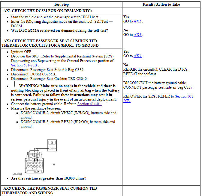
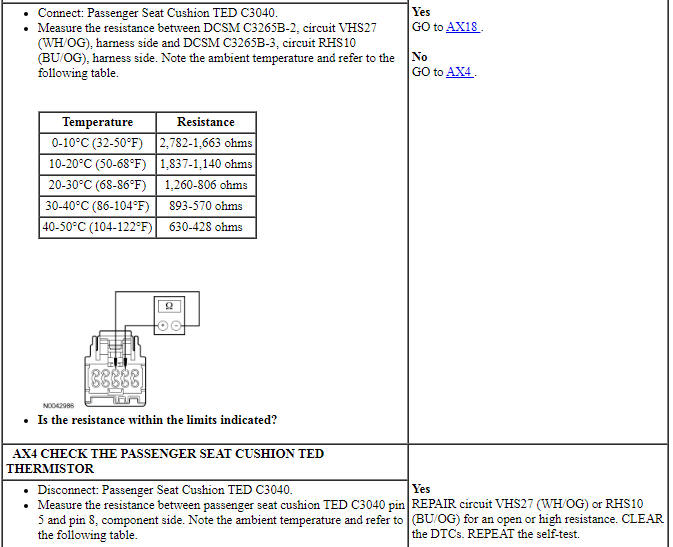
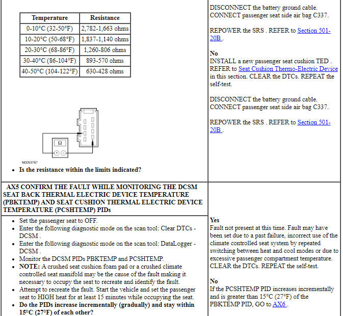
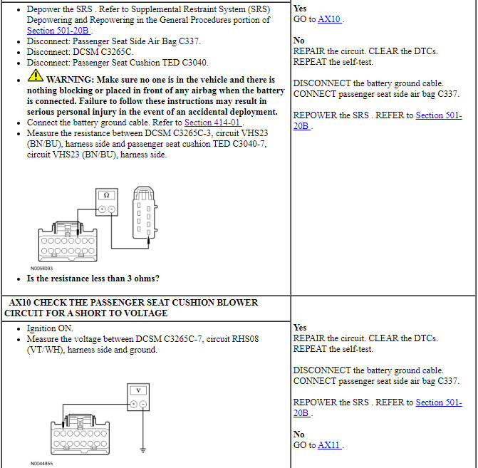
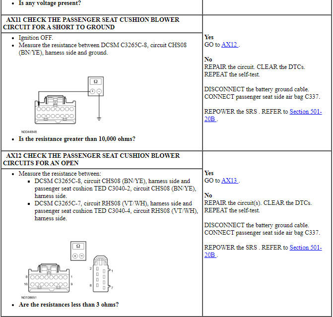
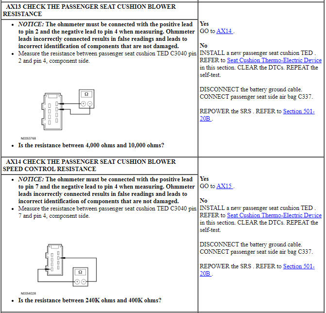
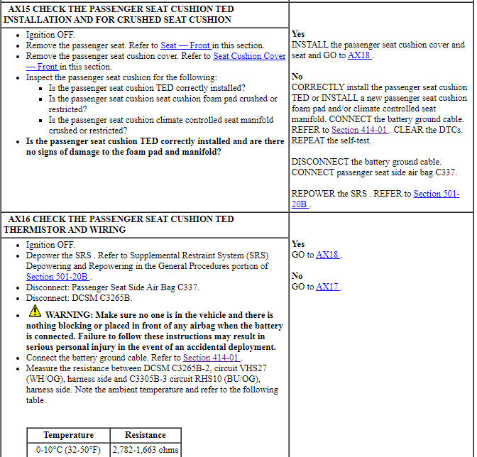
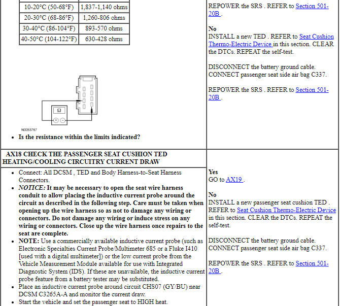
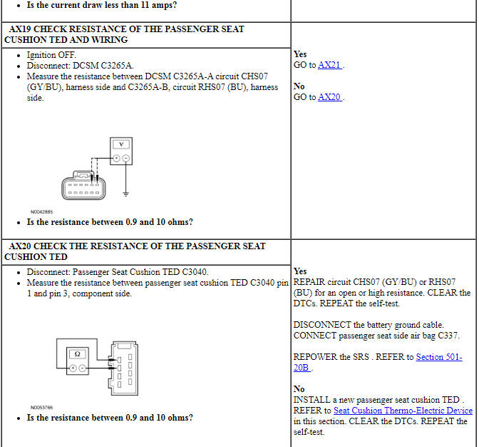
Pinpoint Test AY: DTC B272B
Refer to Wiring Diagrams Cell 119, Climate Controlled Seats for schematic and connector information.
Normal Operation
The Dual Climate Controlled Seat Module (DCSM) monitors seat backrest temperature while it supplies voltage and ground to both blower motors. The DCSM also supplies a variable voltage signal to control the blower speed. Cabin air enters the blower through a filter attached to the Thermo-Electric Device (TED) housing. Heated or cooled air exits the TED and flows through a manifold attached to the foam pad.
- DTC B272B (Passenger Back Over-Temp Detected) - If the passenger seat backrest TED temperature exceeds 70ÂşC (158ÂşF) in cool mode or 85ÂşC (185ÂşF) in heat mode for more than 34 seconds the DCSM shuts down the passenger seat system and sets this DTC.
-
This pinpoint test is intended to diagnose the following:
- Wiring, terminals or connectors
- Restricted backrest TED filter
- Crushed or restricted backrest foam pad
- Crushed or restricted climate controlled seat manifold
- Backrest TED assembly
- DCSM
PINPOINT TEST AY: DTC B272B
NOTICE: When taking measurements at Dual Climate Controlled Seat Module (DCSM) harness connectors, do not insert the electrical probes into the female connector pins. Inserting the probes into connector pins can cause intermittent or open electrical connections after reassembly resulting in Diagnostic Trouble Codes (DTCs) and system failure. Touching the tip of these connector pins is recommended instead.
NOTE: The air bag warning indicator illuminates when the correct Restraints Control Module (RCM) fuse is removed and the ignition is ON.
NOTE: The Supplemental Restraint System (SRS) must be fully operational and free of faults before releasing the vehicle to the customer.
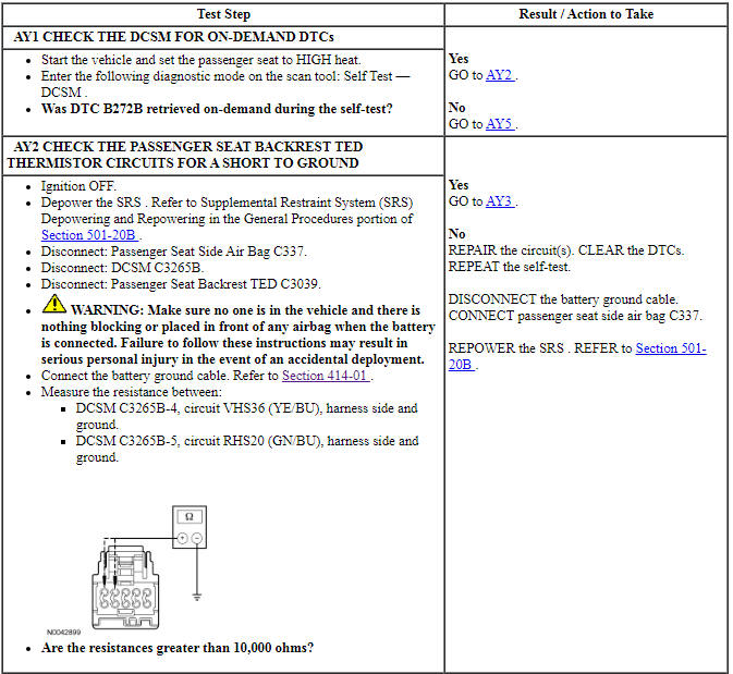
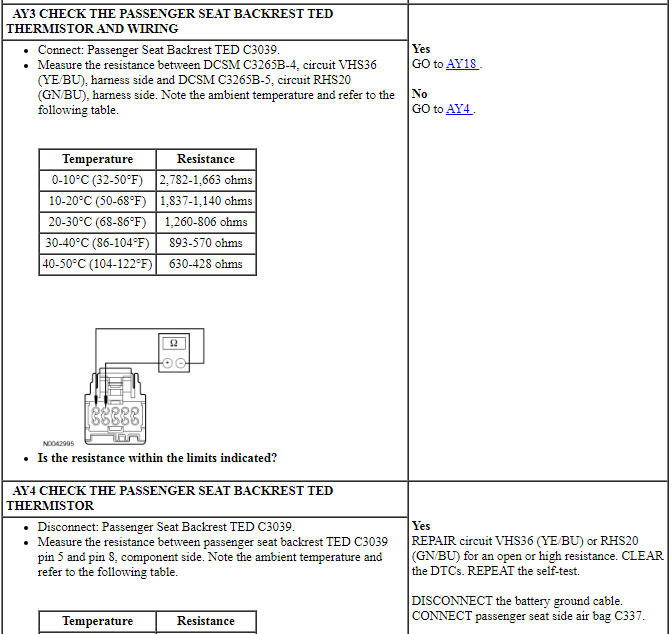
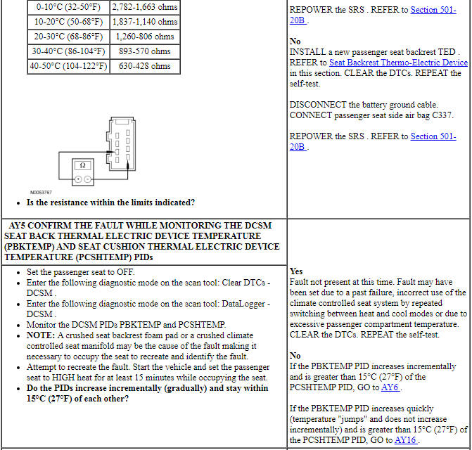
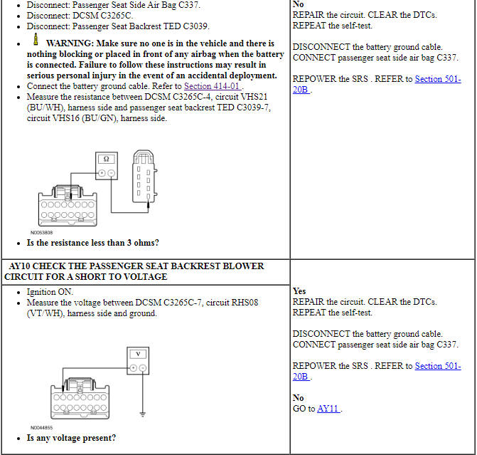
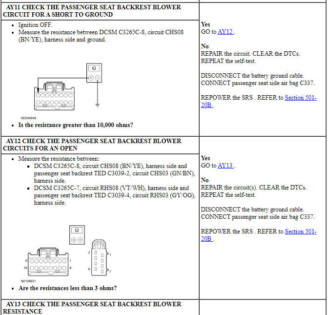
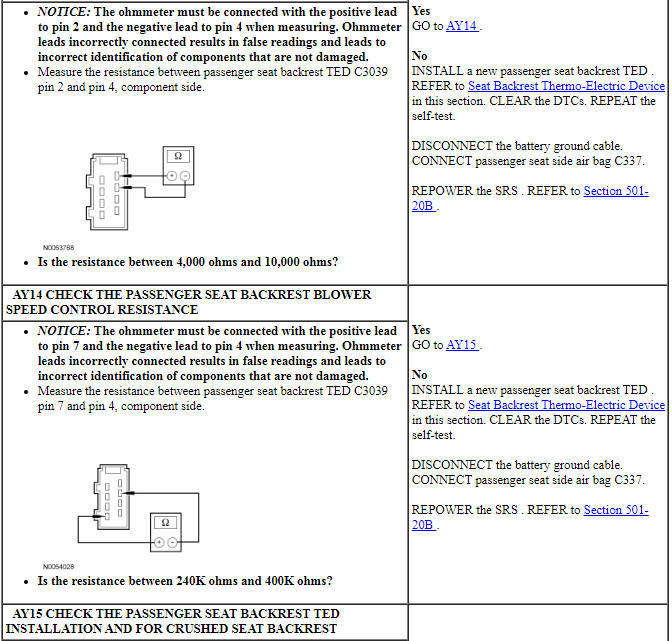
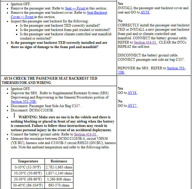
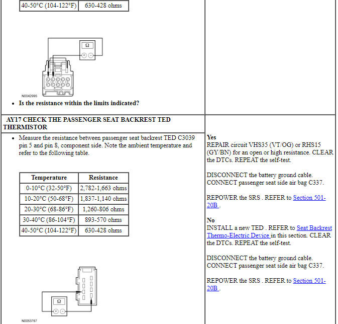
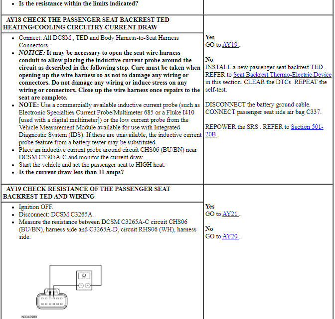
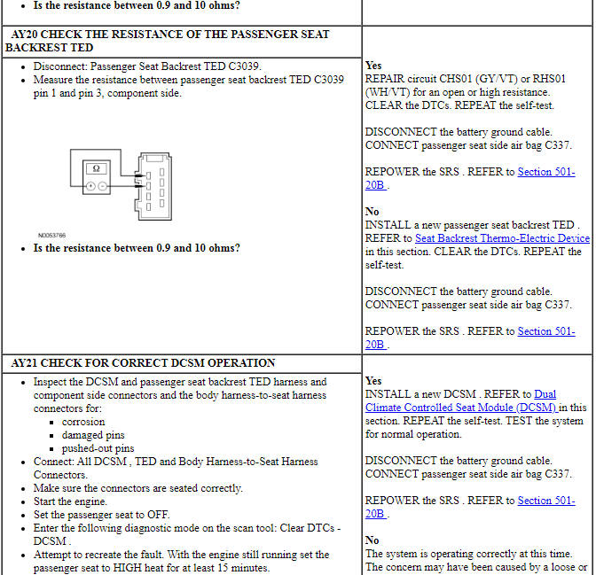
Pinpoint Test AZ: DTC B272C
Refer to Wiring Diagrams Cell 119, Climate Controlled Seats for schematic and connector information.
Normal Operation
The Dual Climate Controlled Seat Module (DCSM) is supplied voltage at all times, but the climate controlled seat system only operates with the engine running. The system can be operated with the ignition ON engine OFF by using a scan tool to bypass the climate controlled seat buttons on the touchscreen interface. When commanding a heat or cool mode operation in this manner, the climate controlled seat system only operates in 15 second intervals. Both voltage supply circuits are spliced together internal to the DCSM, so if one circuit becomes open, both seats can still be operated. However, if a fault occurs setting a DTC specific to either climate controlled seat, only the affected seat is disabled by the DCSM.
The seat cushion is equipped with a Thermo-Electric Device (TED) assembly that includes a seat blower (fan motor, serviced as an assembly with the TED ). Similarly, the seat backrest is also equipped with its own TED assembly with blower. Cabin air is drawn through the blower and distributed to each of the TED modules located in the seat cushion and backrest. The TEDs then heat or cool the air. The air is then directed into the foam pad and manifold where it is distributed along the surface of the cushion and backrest of the seat. Once the system is activated, the DCSM uses a set of flexible algorithms to control the heating/cooling modes and the blower speed dependant on the commanded climate controlled seat settings.
A differential fault occurs when the cushion and backrest TEDs on an affected seat are reporting very different temperatures to the DCSM. This may result from an air flow restriction or a circuit fault of either TED area. If a TED and manifold is clear of obstruction and is operational, check the other TED and circuitry on the seat. It is important to note that a TED with a higher temperature may be operating correctly and not the area of concern. The other TED may be indicating a much lower temperature, causing the DTC to set.
- DTC B272C (Driver Differential Temperature Fault) - If there is a temperature differential between the driver backrest and cushion TED of 60ÂşC (108ÂşF) or more for more than 4 seconds, the TED is disconnected or the duct is blocked, this DTC sets. When this happens the first time in a key cycle, the DCSM puts the driver seat system into recovery mode (see Principles of Operation). If the system is able to recover, it functions normally. If the system is able to recover and it occurs a second time in the same key cycle, the DCSM shuts down the driver seat system.
-
This pinpoint test is intended to diagnose the following:
- Wiring, terminals or connectors
- Restricted cushion or backrest TED filter
- Crushed or restricted cushion or backrest foam pad
- Crushed or restricted cushion or backrest climate controlled seat manifold
- Cushion or backrest TED assembly
- DCSM
PINPOINT TEST AZ: DTC B272C
NOTICE: When taking measurements at Dual Climate Controlled Seat Module (DCSM) harness connectors, do not insert the electrical probes into the female connector pins. Inserting the probes into connector pins can cause intermittent or open electrical connections after reassembly resulting in Diagnostic Trouble Codes (DTCs) and system failure. Touching the tip of these connector pins is recommended instead.
NOTE: The air bag warning indicator illuminates when the correct Restraints Control Module (RCM) fuse is removed and the ignition switch is ON.
NOTE: The Supplemental Restraint System (SRS) must be fully operational and free of faults before releasing the vehicle to the customer.
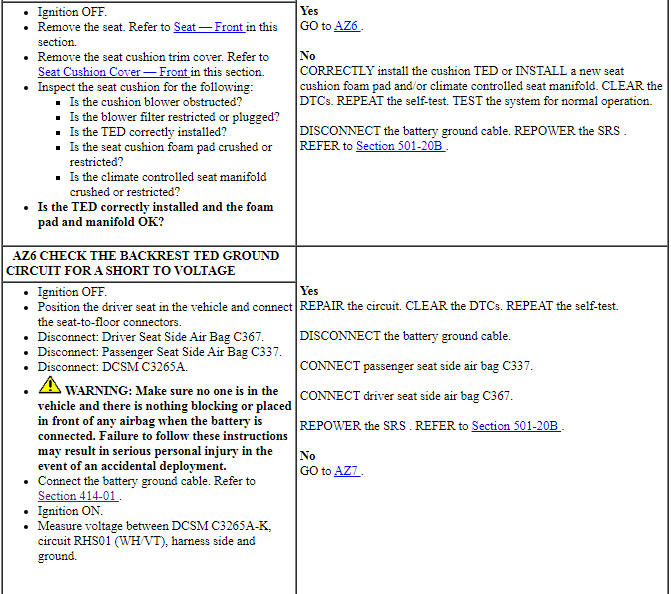
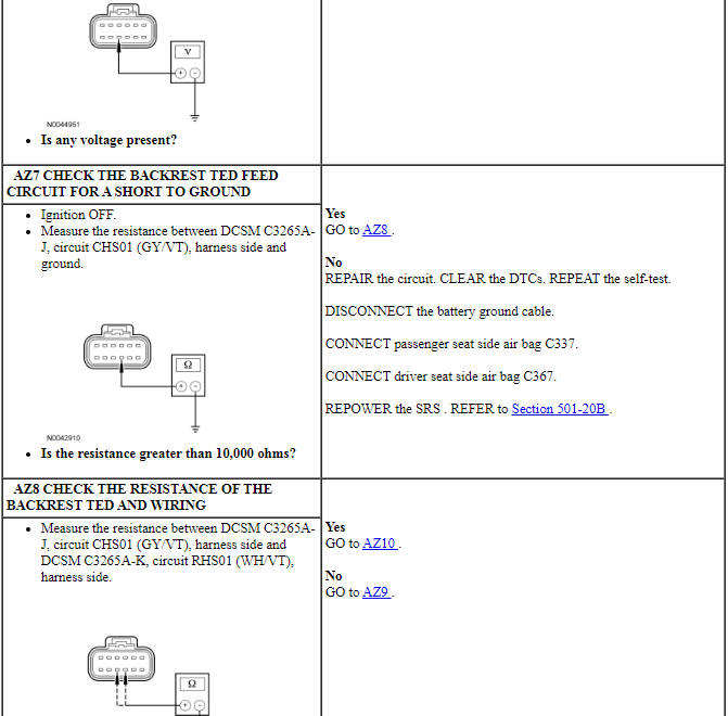
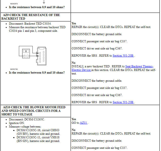
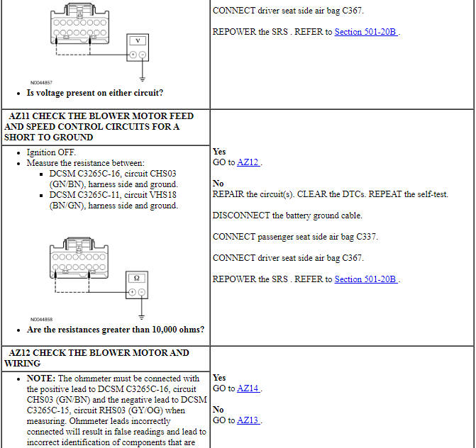
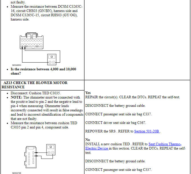
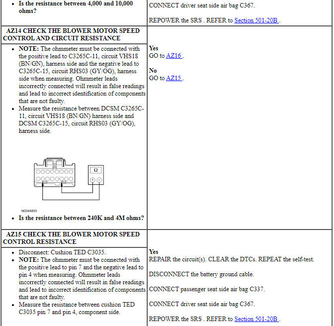
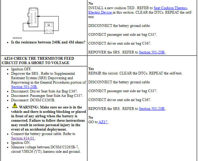
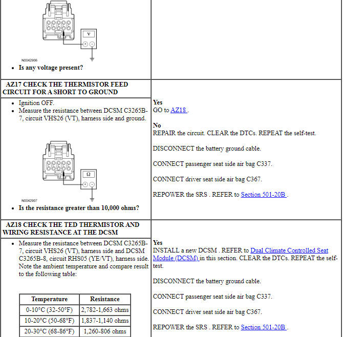
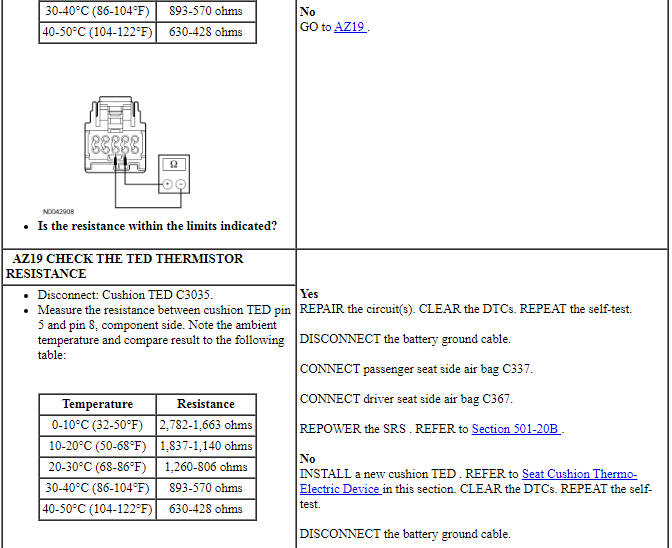
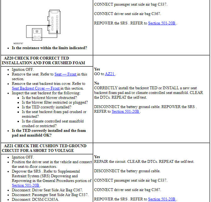
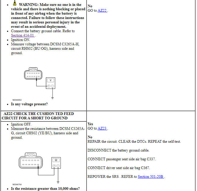
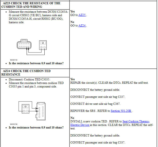
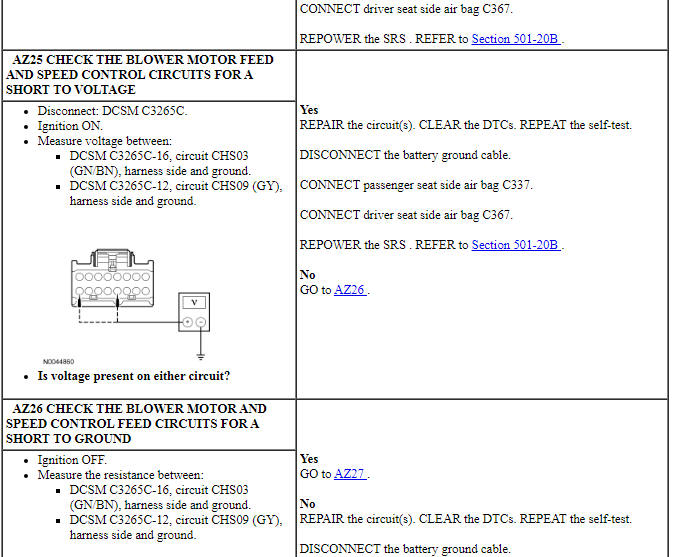
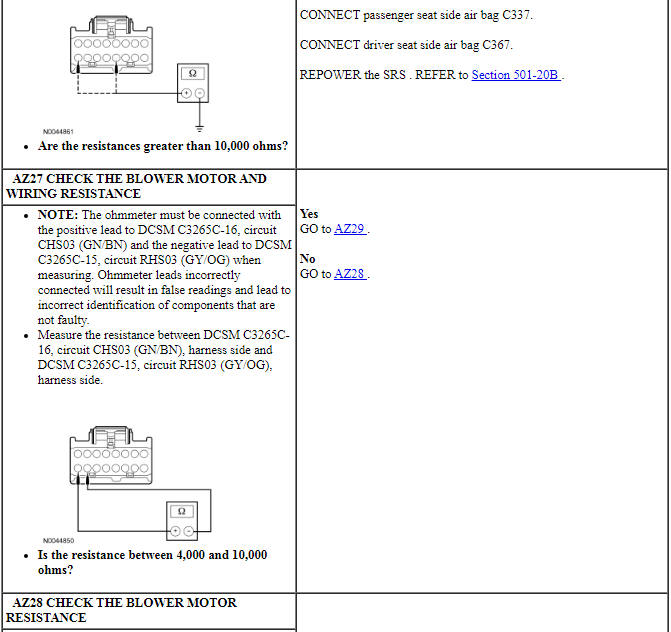
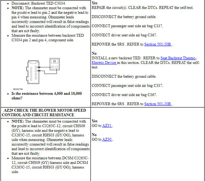
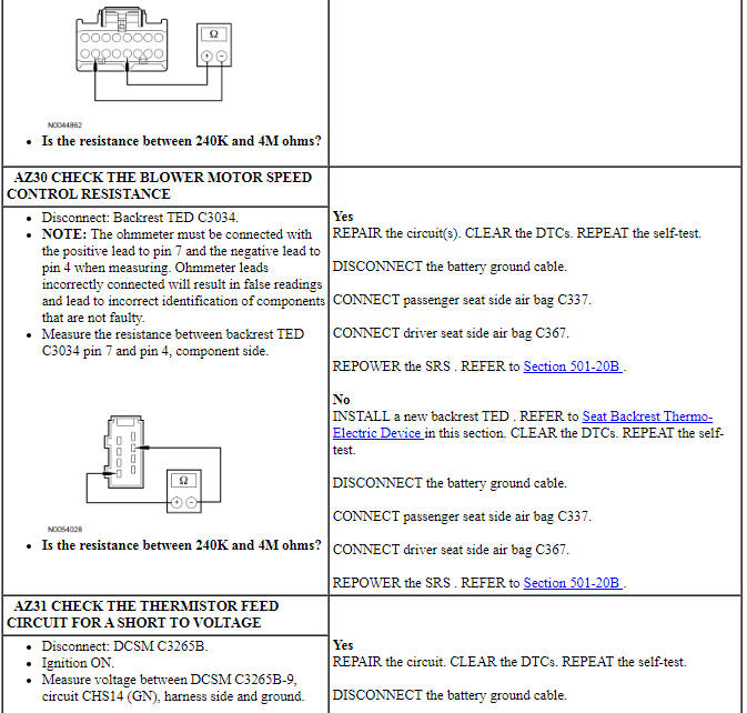
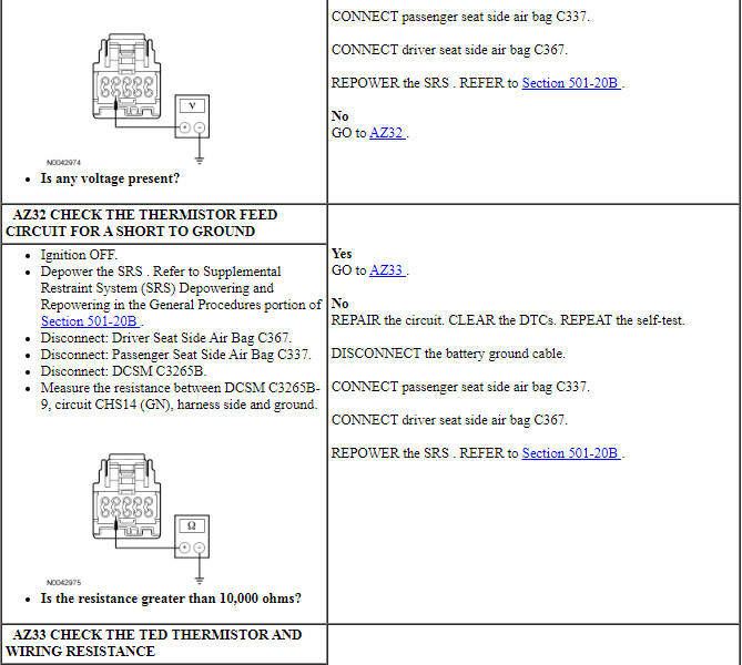
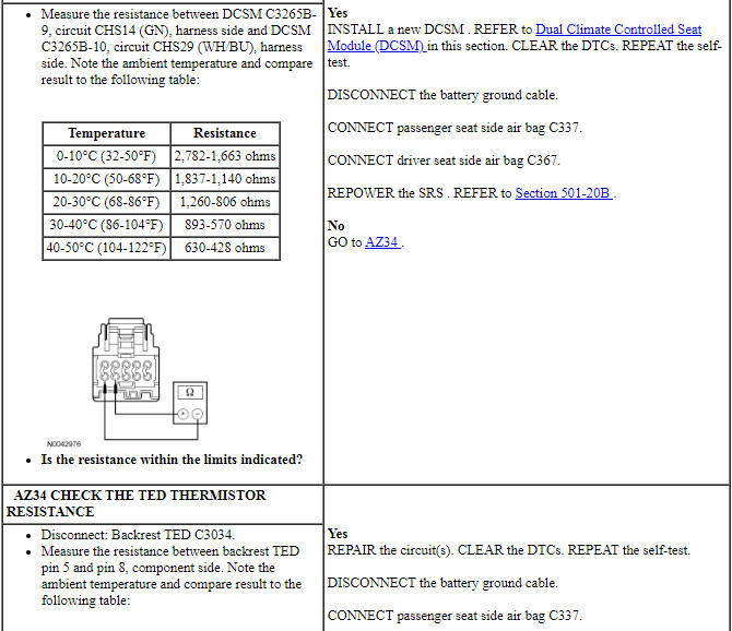
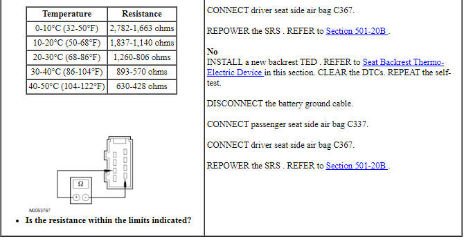
Pinpoint Test BA: DTC B272D
Refer to Wiring Diagrams Cell 119, Climate Controlled Seats for schematic and connector information.
Normal Operation
The Dual Climate Controlled Seat Module (DCSM) is supplied voltage at all times, but the climate controlled seat system only operates with the engine running. The system can be operated with the ignition ON engine OFF by using a scan tool to bypass the climate controlled seat buttons on the touchscreen interface. When commanding a heat or cool mode operation in this manner, the climate controlled seat system only operates in 15 second intervals. Both voltage supply circuits are spliced together internal to the DCSM, so if one circuit becomes open, both seats can still be operated. However, if a fault occurs setting a DTC specific to either climate controlled seat, only the affected seat is disabled by the DCSM.
The seat cushion is equipped with a Thermo-Electric Device (TED) assembly that includes a seat blower (fan motor, serviced as an assembly with the TED ). Similarly, the seat backrest is also equipped with its own TED assembly with blower. Cabin air is drawn through the blower and distributed to each of the TED modules located in the seat cushion and backrest. The TEDs then heat or cool the air. The air is then directed into the foam pad and manifold where it is distributed along the surface of the cushion and backrest of the seat. Once the system is activated, the DCSM uses a set of flexible algorithms to control the heating/cooling modes and the blower speed dependant on the commanded climate controlled seat settings.
A differential fault occurs when the cushion and backrest TEDs on an affected seat are reporting very different temperatures to the DCSM. This may result from an air flow restriction or a circuit fault of either TED area. If a TED and manifold is clear of obstruction and is operational, check the other TED and circuitry on the seat. It is important to note that a TED with a higher temperature may be operating correctly and is not the area of concern. The other TED may be indicating a much lower temperature, causing the DTC to set.
- DTC B272D (Passenger Differential Temperature Fault) - If there is a temperature differential between the passenger backrest and cushion TED of 60ÂşC (108ÂşF) or more for more than 4 seconds, the TED is disconnected or the duct is blocked, this DTC sets. When this happens the first time in a key cycle, the DCSM puts the passenger seat system into recovery mode (see Principles of Operation). If the system is able to recover, it functions normally. If the system is able to recover and it occurs a second time in the same key cycle, the DCSM shuts down the passenger seat system.
-
This pinpoint test is intended to diagnose the following:
- Wiring, terminals or connectors
- Restricted cushion or backrest TED filter
- Crushed or restricted cushion or backrest foam pad
- Crushed or restricted cushion or backrest climate controlled seat manifold
- Cushion or backrest TED assembly
- DCSM
PINPOINT TEST BA: DTC B272D
NOTICE: When taking measurements at Dual Climate Controlled Seat Module (DCSM) harness connectors, do not insert the electrical probes into the female connector pins. Inserting the probes into connector pins can cause intermittent or open electrical connections after reassembly resulting in Diagnostic Trouble Codes (DTCs) and system failure. Touching the tip of these connector pins is recommended instead.
NOTE: The air bag warning indicator illuminates when the correct Restraints Control Module (RCM) fuse is removed and the ignition switch is ON.
NOTE: The Supplemental Restraint System (SRS) must be fully operational and free of faults before releasing the vehicle to the customer.
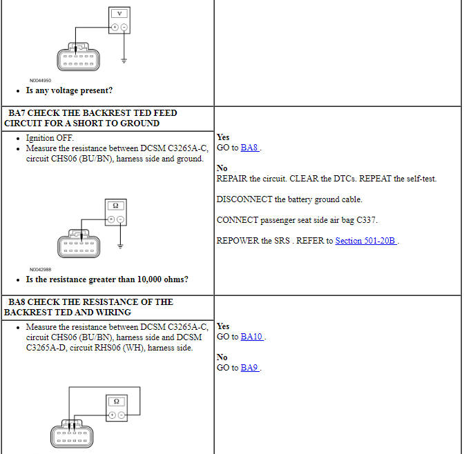
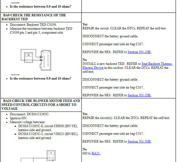
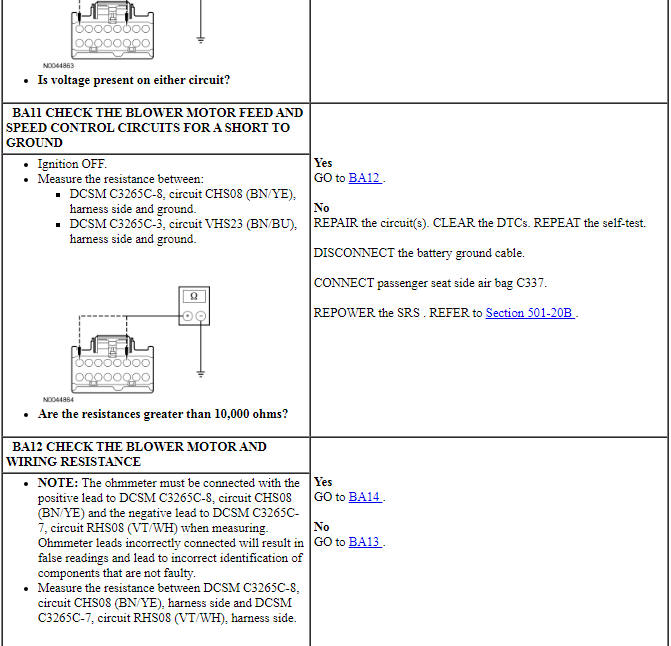
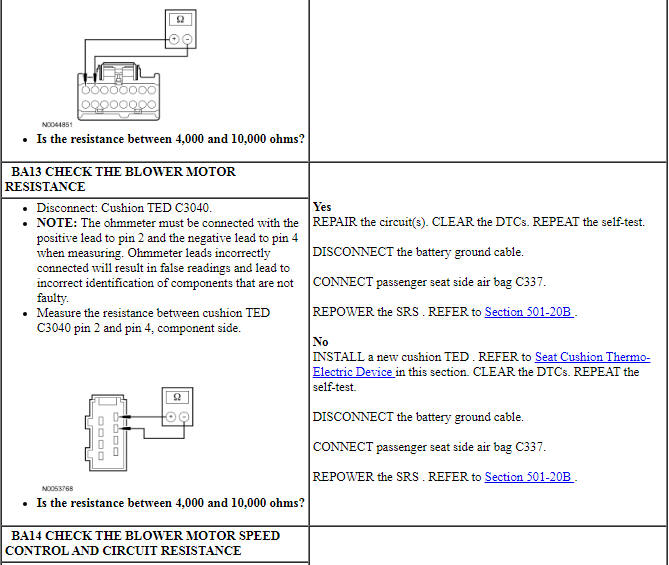
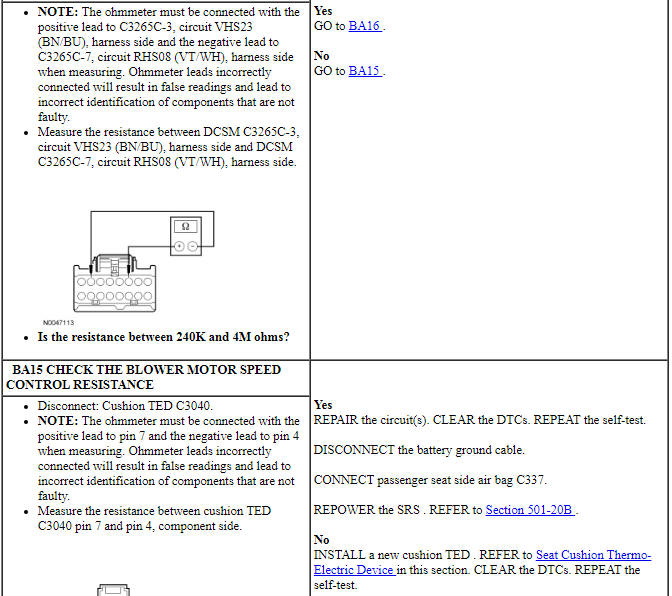
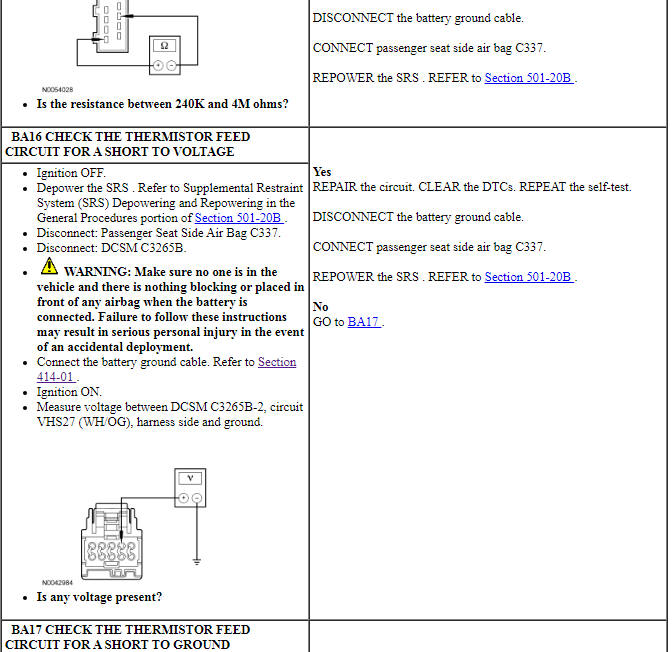
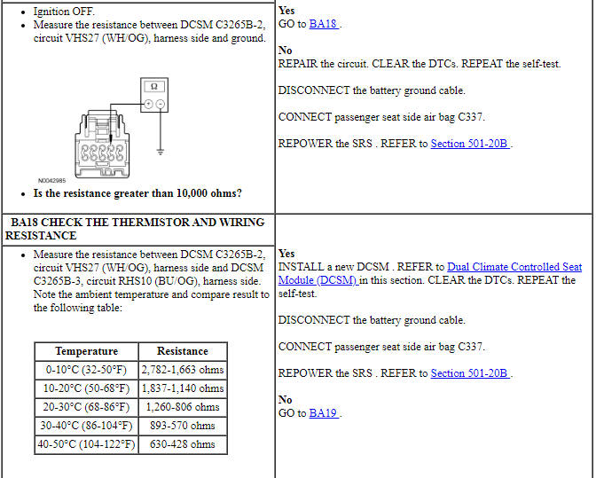
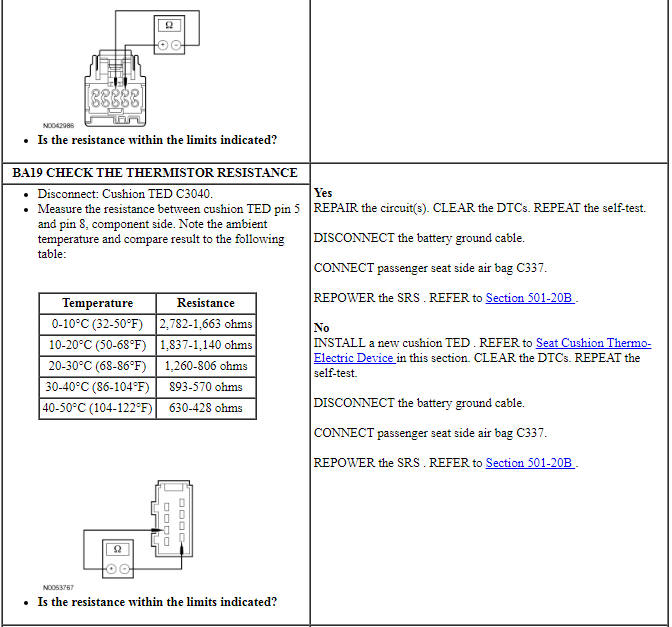
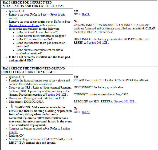
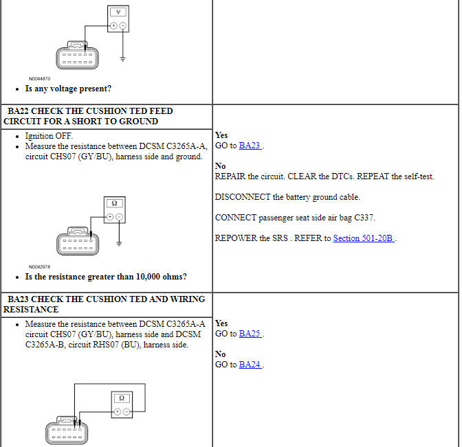
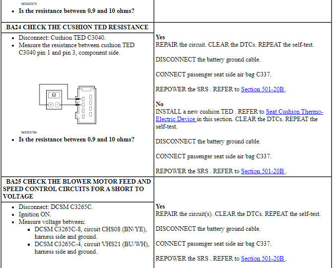
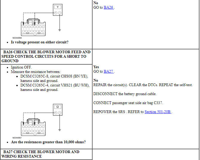
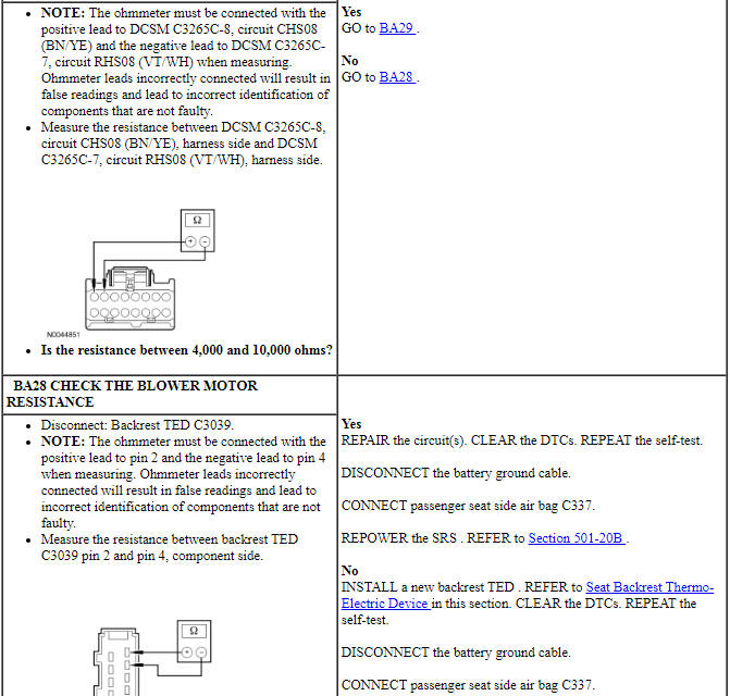
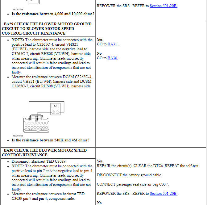
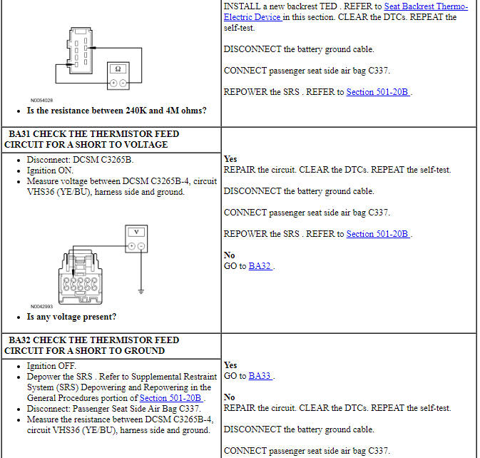
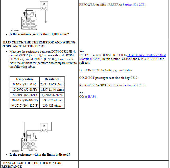
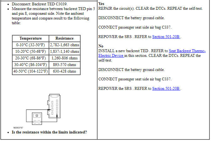
Pinpoint Test BB: DTC B272E
NOTE: This DTC sets for an open or short to voltage. See DTC setting description below.
Refer to Wiring Diagrams Cell 119, Climate Controlled Seats for schematic and connector information.
Normal Operation
The driver climate controlled seat blowers are located within the backrest and cushion Thermo-Electric Devices (TEDs). The Dual Climate Controlled Seat Module (DCSM) supplies voltage and ground to both blowers. The blowers are independently controlled by separate speed control circuits from the DCSM.
- DTC B272E (Driver Ignition Run/Blower Circuit Short to Ground) - If either the blower voltage supply or return circuits are open (to both cushion or backrest blowers) or shorted to voltage, the DTC is set and after 4-6 seconds the DCSM disables outputs to the driver seat. The DTC also sets if the blower voltage supply or return circuit is open to only one blower when DCSM supply voltage is less than 12 volts.
-
This pinpoint test is intended to diagnose the following:
- Wiring, terminals or connectors
- Backrest or cushion TED
- DCSM
PINPOINT TEST BB: DTC B272E
NOTICE: When taking measurements at Dual Climate Controlled Seat Module (DCSM) harness connectors, do not insert the electrical probes into the female connector pins. Inserting the probes into connector pins can cause intermittent or open electrical connections after reassembly resulting in Diagnostic Trouble Codes (DTCs) and system failure. Touching the tip of these connector pins is recommended instead.
NOTE: The air bag warning indicator illuminates when the correct Restraints Control Module (RCM) fuse is removed and the ignition switch is ON.
NOTE: The Supplemental Restraint System (SRS) must be fully operational and free of faults before releasing the vehicle to the customer.
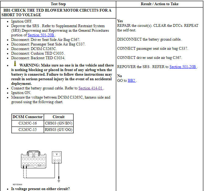
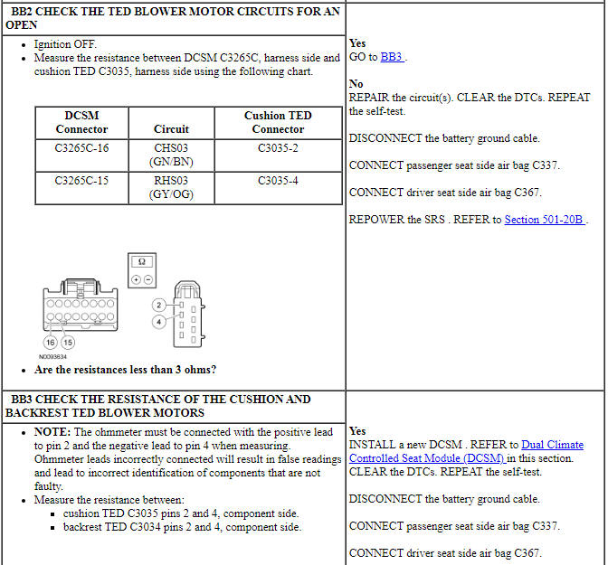
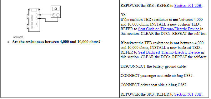
Pinpoint Test BC: DTC B272F
NOTE: This DTC sets for an open or short to voltage. See DTC setting description below.
Refer to Wiring Diagrams Cell 119, Climate Controlled Seats for schematic and connector information.
Normal Operation
The passenger climate controlled seat blowers are located within the backrest and cushion Thermo-Electric Devices (TEDs). The Dual Climate Controlled Seat Module (DCSM) supplies voltage and ground to both blowers. The blowers are independently controlled by separate speed control circuits from the DCSM.
- DTC B272F (Passenger Ignition Run/Blower Circuit Short to Ground) - If either the blower voltage supply or return circuits are open (to both cushion and backrest blowers) or shorted to voltage, the DTC is set and after 4-6 seconds the DCSM disables outputs to the passenger seat. The DTC also sets if the blower voltage supply or return circuit is open to only one blower when DCSM supply voltage is less than 12 volts.
-
This pinpoint test is intended to diagnose the following:
- Wiring, terminals or connectors
- Backrest or cushion TED
- DCSM
PINPOINT TEST BC: DTC B272F
NOTICE: When taking measurements at Dual Climate Controlled Seat Module (DCSM) harness connectors, do not insert the electrical probes into the female connector pins. Inserting the probes into connector pins can cause intermittent or open electrical connections after reassembly resulting in Diagnostic Trouble Codes (DTCs) and system failure. Touching the tip of these connector pins is recommended instead.
NOTE: The air bag warning indicator illuminates when the correct Restraints Control Module (RCM) fuse is removed and the ignition switch is ON.
NOTE: The Supplemental Restraint System (SRS) must be fully operational and free of faults before releasing the vehicle to the customer.
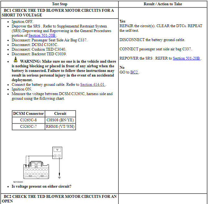
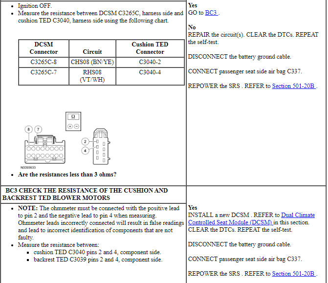
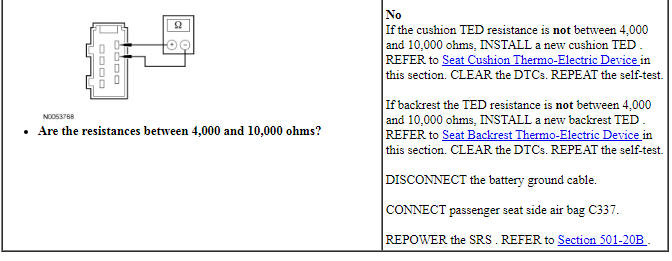
Pinpoint Test BD: DTC B2730
Refer to Wiring Diagrams Cell 119, Climate Controlled Seats for schematic and connector information.
Normal Operation
The Dual Climate Controlled Seat Module (DCSM) monitors seat backrest temperature while it supplies voltage and ground to both blower motors. The DCSM also supplies a variable voltage signal to control the blower speed. Cabin air enters the blower through a filter attached to the Thermo-Electric Device (TED) housing. Heated or cooled air exits the TED and flows through a manifold attached to the foam pad.
- DTC B2730 (Back Over-Temp Detected) - If the driver seat backrest TED temperature exceeds 70ÂşC (158ÂşF) in cool mode or 85ÂşC (185ÂşF) in heat mode for more than 34 seconds the DCSM shuts down the driver seat system and sets this DTC.
-
This pinpoint test is intended to diagnose the following:
- Wiring, terminals or connectors
- Restricted backrest TED filter
- Crushed or restricted backrest foam pad
- Crushed or restricted climate controlled seat manifold
- Backrest TED assembly
- Dual Climate Controlled Seat Module (DCSM)
PINPOINT TEST BD: DTC B2730
NOTICE: When taking measurements at Dual Climate Controlled Seat Module (DCSM) harness connectors, do not insert the electrical probes into the female connector pins. Inserting the probes into connector pins can cause intermittent or open electrical connections after reassembly resulting in Diagnostic Trouble Codes (DTCs) and system failure. Touching the tip of these connector pins is recommended instead.
NOTE: The air bag warning indicator illuminates when the correct Restraints Control Module (RCM) fuse is removed and the ignition is ON.
NOTE: The Supplemental Restraint System (SRS) must be fully operational and free of faults before releasing the vehicle to the customer.
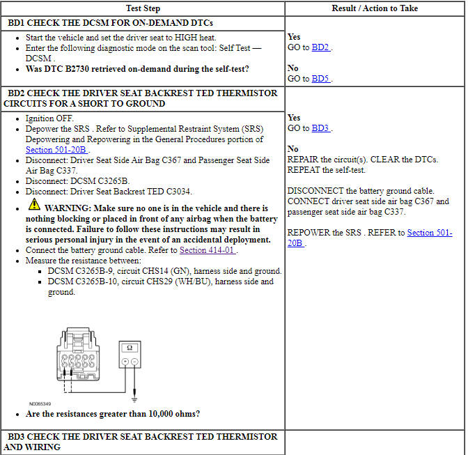
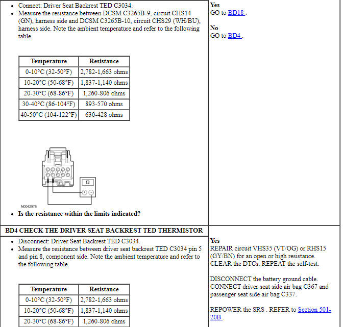
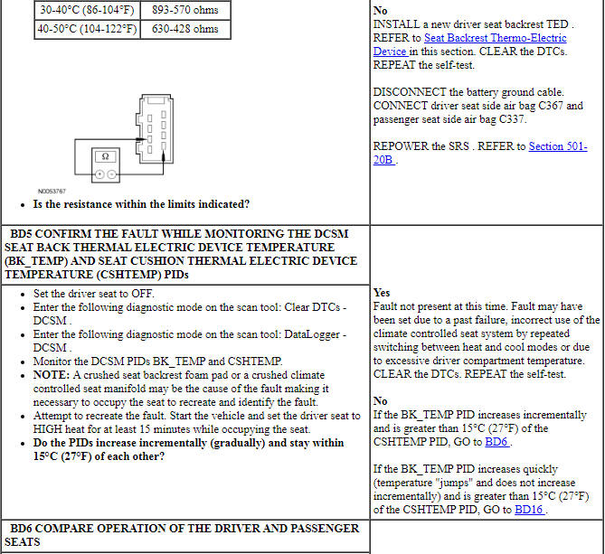
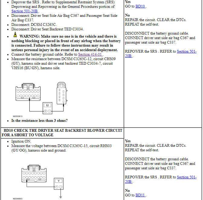
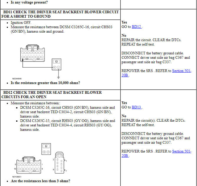
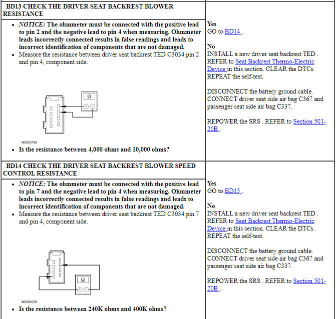
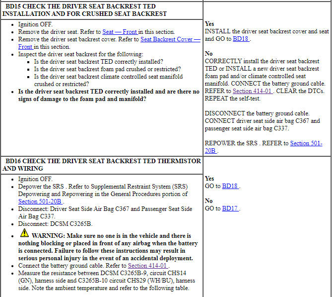
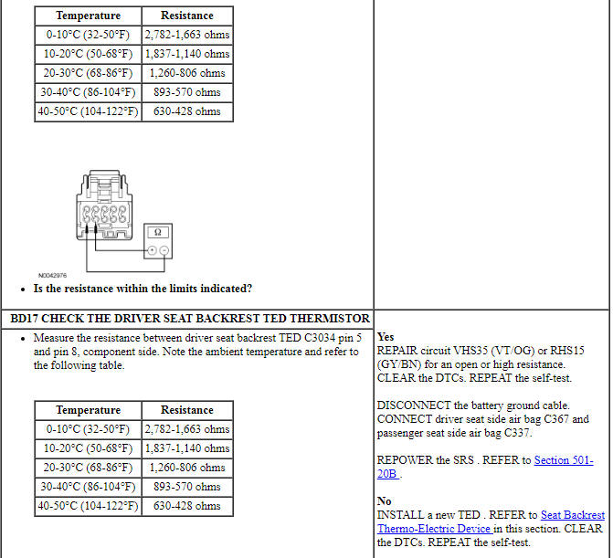
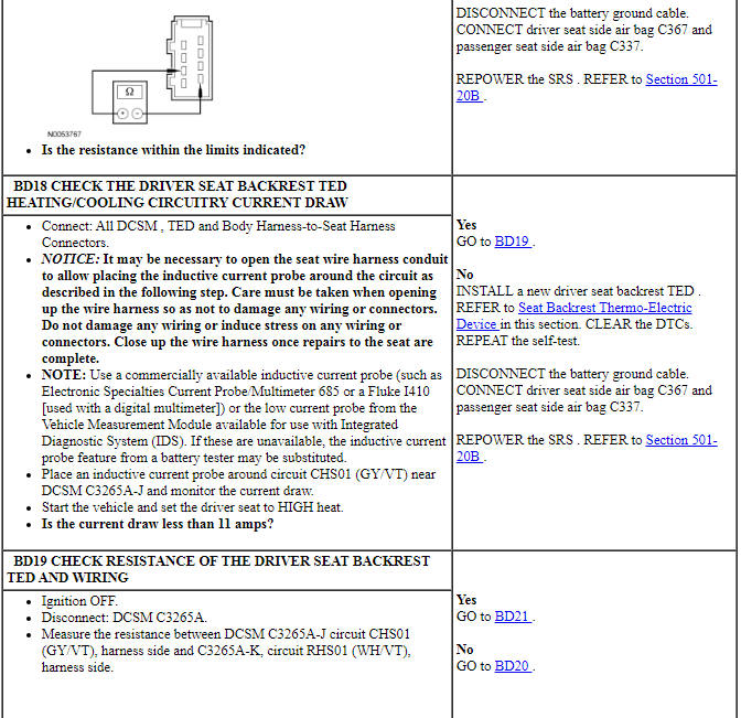
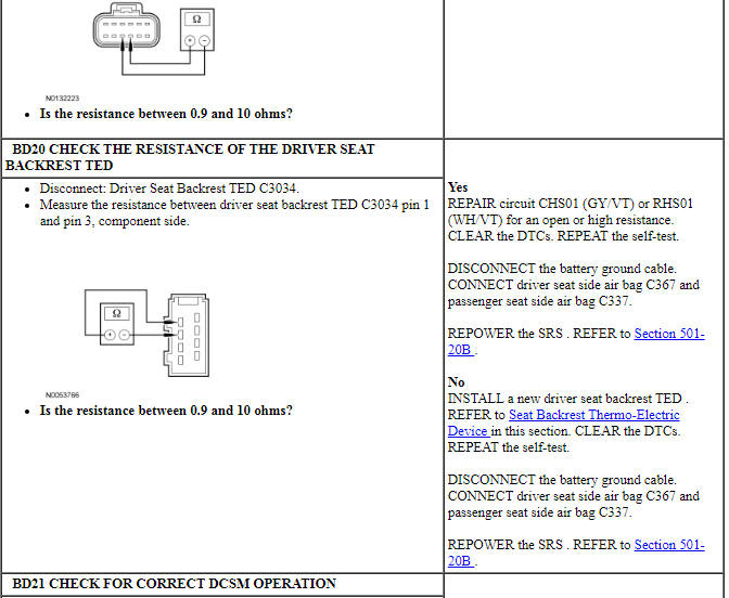
Pinpoint Test BE: DTCs B106E, B106F
Normal Operation
When a repetitive fault causing a circuit overload is detected on certain output circuits, the Driver Seat Module (DSM) disables the circuit by removing voltage or ground to the affected circuit. The circuit remains disabled until the fault is corrected and an on-demand self-test is run. When the on-demand self-test has been run after all faults have been corrected, any DTCs related to the fault are cleared.
- DTC B106E (Solid State Driver Disabled Due to Short Circuit) - a continuous DTC that sets when the DSM has disabled a circuit due to a repetitive fault causing a circuit overload.
- DTC B106F (Module Disabled Due to External Fault) - a continuous DTC that sets when one or more output functions are permanently disabled due to a repetitive circuit overload fault. DTC B106F sets with DTC B106E. When DTC B106F is present, the DSM must be replaced after the fault condition has been corrected.
This pinpoint test is intended to diagnose the following:
- Output circuit short to ground or voltage
- DSM
PINPOINT TEST BE: DTCs B106E, B106F
NOTICE: If DTC B106F is present and the Driver Seat Module (DSM) is being replaced, the fault condition must be corrected first. Failure to correct the fault condition first may cause damage to the new DSM, resulting in a repeat repair.
Pinpoint Test BF: DTC B1317
Refer to Wiring Diagrams Cell 123, Memory Seats for schematic and connector information.
Normal Operation
The Driver Seat Module (DSM) continuously monitors the input voltage for correct operation. If the DSM detects input voltage below 11 volts, it stores DTC B1318 in memory. If the DSM detects input voltage above 15 volts, it stores DTC B1317 in memory. If DTC B1317 or B1318 is set, the DSM disables the memory system outputs for the driver seat memory operation.
- DTC B1317 (Battery Voltage High) - This DTC sets if the DSM detects voltage above 15 volts.
-
This pinpoint test is intended to diagnose the following:
- Wiring, terminals or connectors
- DSM
PINPOINT TEST BF: DTC B1317
NOTE: DTC B1317 may be stored in the module memory due to previous battery charging or vehicle jump starting events.
Pinpoint Test BG: DTC B1318
Refer to Wiring Diagrams Cell 123, Memory Seats for schematic and connector information.
Normal Operation
The Driver Seat Module (DSM) continuously monitors the input voltage for correct operation. If the DSM detects input voltage below 11 volts, it stores DTC B1318 in memory. If the DSM detects input voltage above 15 volts, it stores DTC B1317 in memory. If DTC B1317 or B1318 is set, the DSM disables the memory system outputs for the driver seat memory operation.
- DTC B1318 (Battery Voltage Low) - This DTC sets if the DSM detects voltage below 11 volts.
-
This pinpoint test is intended to diagnose the following:
- Wiring, terminals or connectors
- DSM
PINPOINT TEST BG: DTC B1318
NOTICE: Use the correct probe adapter(s) when making measurements. Failure to use the correct probe adapter(s) may damage the connector.
NOTE: Failure to disconnect the battery when instructed will result in false resistance readings. Refer to Section 414-01.
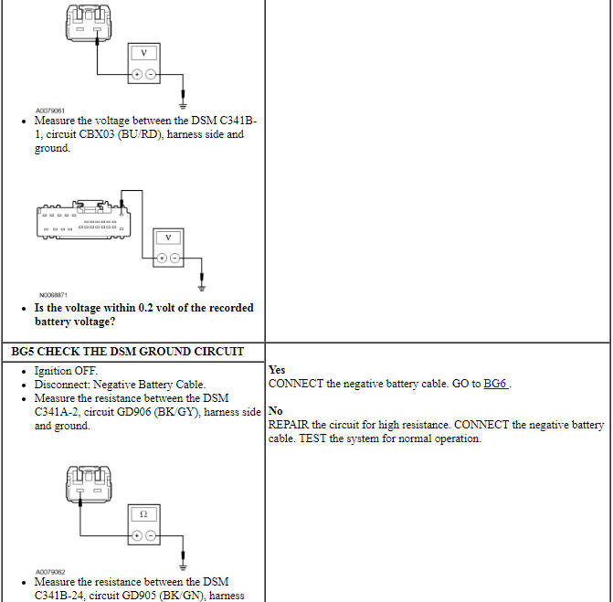
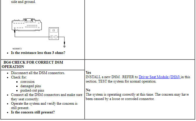
Pinpoint Test BH: DTC U0140
Refer to Wiring Diagrams Cell 14, Module Communications Network for schematic and connector information.
Normal Operation
The Driver Seat Module (DSM) and the BCM communicate using the Medium Speed Controller Area Network (MS-CAN). Messages are exchanged between the modules on the MS-CAN.
- DTC U0140 (Lost Communication With Body Control Module ( GEM ) ) - set by the DSM whenever it has lost communication to the BCM for 15 seconds or longer as long as the module voltage is between 10 and 15 volts.
This pinpoint test is intended to diagnose the following:
- Module communication
- DSM
- BCM
PINPOINT TEST BH: DTC U0140
Component Test
Component Testing - Thermo-Electric Device (TED) Cooling Performance
NOTE: This test is intended to check the cooling mode performance of an operational climate controlled seat backrest or cushion Thermo-Electric Device (TED) and verify it is cooling inlet air at the TED (ambient cabin air) between 6-8ÂşC (10-14ÂşF).
NOTE: Make sure the vehicle is out of direct sunlight and is in an area with a stable air temperature when testing the climate controlled seat system.
NOTE: For correct temperature measurements, the seat being tested should be occupied.
- Enter DataLogger and monitor the following DCSM PIDs:
- CSHTEMP (Seat cushion thermal electric device temperature)
- BK_TEMP (Seat back thermal electric device temperature)
- PCSHTMP (Passenger Cushion Thermal Electric Device [TED] Temperature)
- PBKTMP (Passenger Back (TED) Temperature)
- DCCSMOD (Driver State Seat Mode)
- PCCSMOD (Passenger State Seat Mode)
- Any initial PID value of greater than 205ÂşC (401ÂşF) or less than 2ÂşC (36ÂşF) indicates a system hardware failure. Do not proceed with this test. GO to Symptom Chart or Dual Climate Controlled Seat Module (DCSM) DTC Chart for diagnosis.
- NOTE: Typical backrest and cushion TED shown.
Gain access to the seat backrest and cushion TEDs and use a suitable thermo-couple temperature measuring device to monitor the air inlet temperature.
- Access the backrest TED.
- Detach the backrest cover lower J-clips and route the wire harness(es), manual lumbar cable (if equipped) and air hoses (if equipped) out of the hole(s) in the backrest cover.
- On each side, separate the backrest cover clip and hook-and-loop strips.
- Separate the hook-and-loop strips, invert the backrest cover up and remove the 3 first row hog rings.
- Separate the hook-and-loop strips, invert the backrest cover up as far as it will go.
- Place the temperature probe near each TEDs air filter.
- Access the backrest TED.
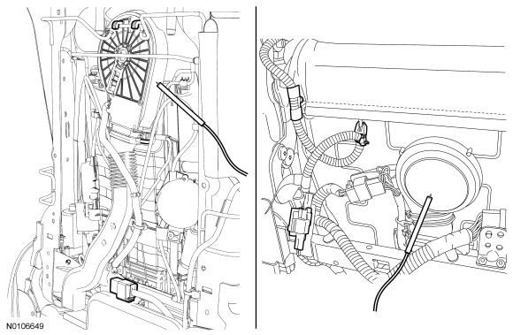
- NOTE: The engine must be running to operate the climate
controlled seat system and carry out this test.
Operate system in high cool mode and measure the temperature at the cushion TED filter using the thermo-couple device.
- Obtain and record the air inlet temperature at the TED.
- Use a scan tool to measure the cushion TED PID temperature and record
the value.
- Monitor the MODE PID and verify the system is operating. If during testing the PID value changes to Blower Only state, the system has entered into recovery mode and voltage to the TEDs is disabled. If this occurs, the seat has failed the test. Do not continue. Return to the diagnostic routine.
- Subtract the cushion TED PID temperature from the cushion air inlet temperature and record the temperature difference value.
- Continue to operate the system in high cool mode and use the
thermo-couple device to measure the temperature at the backrest TED filter.
- Obtain and record the air inlet temperature at the TED.
- Secure the temperature probe at the backrest TED air filter and close the backrest trim cover before measuring.
- Obtain and record the air inlet temperature at the TED.
- Use a scan tool to measure the backrest TED PID temperature and record
the value.
- Monitor the MODE PID and verify the system is operating. If during testing the PID value changes to Blower Only state, the system has entered into recovery mode and voltage to the TEDs is disabled. If this occurs, the seat has failed the test. Do not continue. Return to the diagnostic routine.
- Subtract the backrest TED PID temperature from the backrest air inlet temperature and record the value.
- Compare the cushion and backrest calculated temperature values. Both values should be between 6Âş-8ÂşC (10.8Âş-14.4ÂşF) and approximately equal (+-1ÂşC [+-1.8ÂşF] ).
- If the calculated temperature values are not within these specifications, check the climate controlled seat components for air duct or filter restrictions, blockages, duct or electrical disconnections and for incorrect assembly. Repair as needed. If OK, carry out the DCSM self-test and if any DTC is retrieved, go to Dual Climate Controlled Seat Module (DCSM) DTC Chart for diagnostic direction. Return to the diagnostic routine.
 Specifications, Description and Operation
SPECIFICATIONS
Torque Specifications
a Refer to the procedure in this section.
DESCRIPTION AND OPERATION
Seating
Front Seats
The front seats can be equipped with the following systems:
Manual ...
 General Procedures
Accessing Mounting Bolts On an Inoperative Power Seat
General Equipment
Drill(s)
WARNING: Wear protective gloves when handling components or parts that
have pointed or sharp edges. Failure to foll ...
Other materials:
Disassembly and Assembly of Subassemblies
Cylinder Head
Special Tool(s)
Material
Disassembly
NOTICE: During engine repair procedures, cleanliness is extremely
important. Any foreign material, including any material created while cleaning
gasket surfaces, that enters the oil passages, coolant passages or the oil pan
can cause en ...
Adjusting the steering wheel
WARNING: Do not adjust the steering wheel when your vehicle
is moving.
Note: Make sure that you are sitting in the correct position. See
Sitting
in the Correct Position in the Seats chapter.
1. Unlock the steering column.
2. Adjust the steering wheel to the
desired position.
3. Lock t ...
Bumpers
SPECIFICATIONS
Torque Specifications
REMOVAL AND INSTALLATION
Bumper Cover - Front
Removal
With the vehicle in NEUTRAL, position it on a hoist. For additional
information, refer to Section 100-02.
NOTE: Three on each side.
NOTE: If equipped.
NOTE:&n ...
