SPECIFICATIONS
Torque Specifications
REMOVAL AND INSTALLATION
Bumper Cover - Front
Removal
- With the vehicle in NEUTRAL, position it on a hoist. For additional information, refer to Section 100-02.
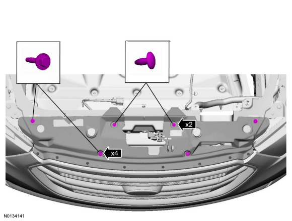
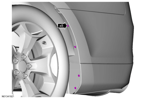
- NOTE: Three on each side.
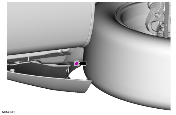
- NOTE: If equipped.
- NOTE: If equipped.
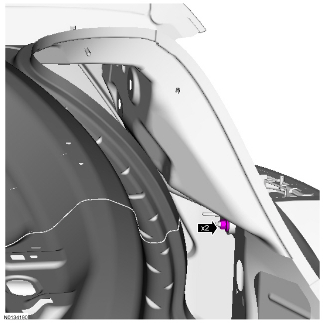
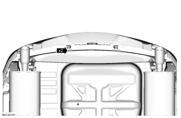
- NOTE: One on each side.
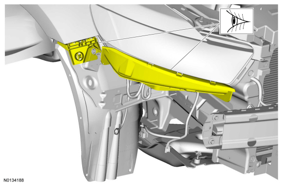
- NOTE: The rearward upper portion of the bumper cover must be pulled outward and downward to unclip it from the fender.
- If necessary, install new bumper cover mounting brackets.
Installation
- To install, reverse the removal procedure.
Bumper - Front
Removal
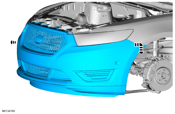
- Remove the front bumper cover. For additional information, refer to Bumper Cover - Front.
- If equipped, remove the active grille shutter assembly. For additional information refer to Section 501-02.
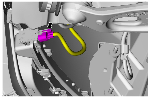
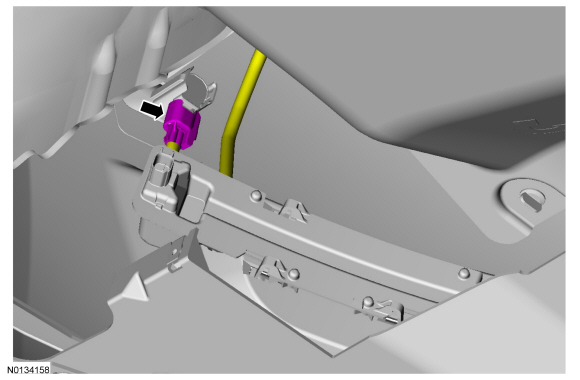
- NOTE: The removal of the speed control sensor or the cruise
control sensor bracket will require vertical alignment of the cruise control
sensor and Cruise-Control Module (C-CM) Calibration when reinstalled.
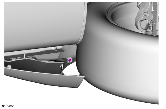
If equipped, remove the cruise control sensor and bracket. For additional information, refer to Section 413-13B.
- If equipped.
- To install, tighten to 8 Nm (71 lb-in).
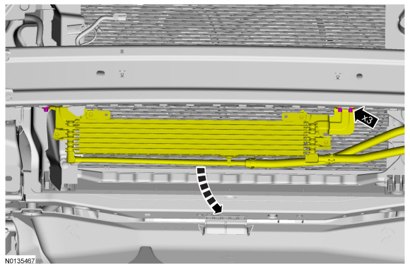
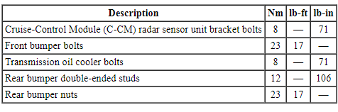
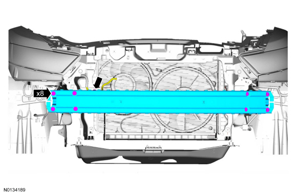
- NOTE: There are 2 tack welds on each side of the front bumper. These welds must be drilled out to remove the beam.
- NOTE: Tack welds retaining the front bumper to the body rails are
not required for installation. Install new front bumper bolts.
- To install, tighten to 23 Nm (17 lb-ft).
Installation
- To install, reverse the removal procedure.
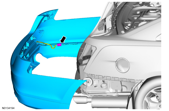
Bumper Cover - Rear
Removal
- With the vehicle in NEUTRAL, position it on a hoist. For additional information, refer to Section 100-02.
- Remove the rear taillamps. For additional information, refer to Section 417-01.
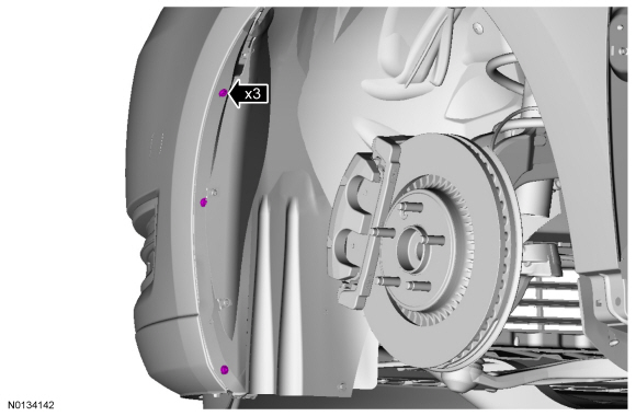
- NOTE: Four on each side.
- NOTE: On each side.
- NOTE: Pull upward beneath the tail lamps to release the bumper cover upper clips.
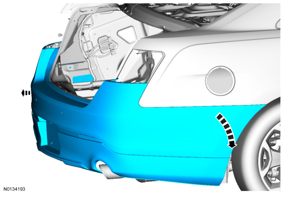
- NOTE: Inspect the lower back sheet metal for distortion.
- NOTE: If necessary, install new bumper cover mounting reinforcements before installation.
Installation
- To install, reverse the removal procedure.
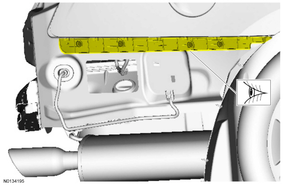
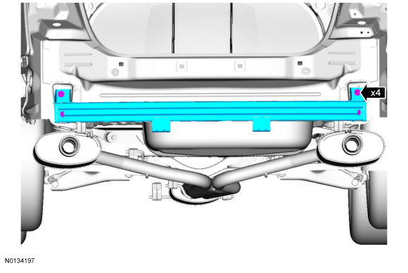
Bumper - Rear
Removal
- Remove the rear bumper cover. For additional information, refer to Bumper Cover - Rear.
- NOTE: Inspect the rear bumper double-ended studs for damage. If
necessary, install new rear bumper double-ended studs.
NOTE: Anytime the rear bumper nuts are removed, it is necessary to re-tighten the rear bumper double-ended studs.
- Tighten the rear bumper nuts to 23 Nm (17 lb-ft).
- Tighten the rear bumper double-ended studs to 12 Nm (106 lb-in).
Installation
- To install, reverse the removal procedure.
 Removal and Installation
Roof Opening Panel - Exploded View
NOTE: The roof opening panel motor must be initialized when repairs
are carried out on any part of the roof opening panel system, including:
whenever the roof ...

Other materials:
Heated windows and mirrors (if equipped)
Heated Rear Window
Note: The ignition must be switched on to use this feature.
Press the button to clear the rear window of thin ice and fog. Press the
button again within 10 minutes to switch it off. It switches off
automatically after 10 minutes, or when you switch the ignition off.
Do no ...
Heated and ventilated seats
Heated Seats
WARNING: Persons who are unable to feel pain to the skin
because of advanced age, chronic illness, diabetes, spinal cord
injury, medication, alcohol use, exhaustion, or other physical conditions,
must exercise care when using the seat heater. The seat heater may
cause burns even at ...
Engine Ignition - 3.5L Ti-VCT
SPECIFICATIONS
Material
General Specifications
Torque Specifications
DESCRIPTION AND OPERATION
Engine Ignition
Component Location
System Operation
REFER to the PC/ED manual
section 1 Description and Operation.
Component Description
REFER to the PC/ED manual
section 1 Descr ...
