Engine
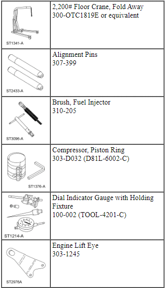
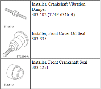
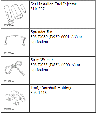
Special Tool(s)
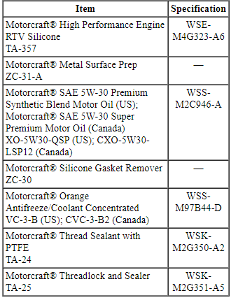
Material
Engine Upper
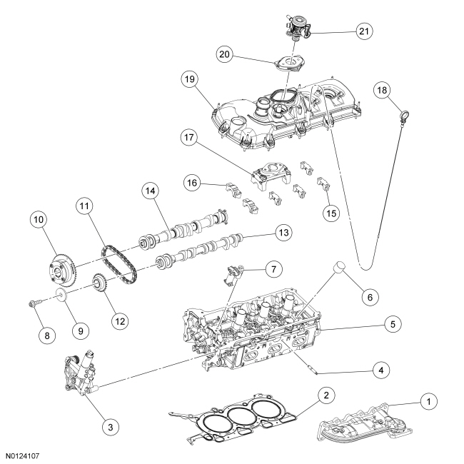
Engine Upper - LH Cylinder Head
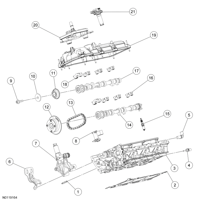
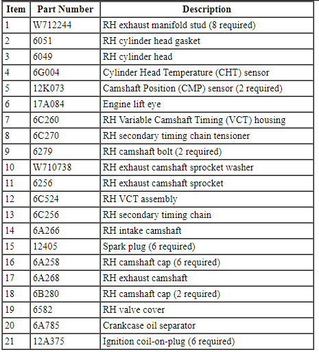
Engine Upper - RH Cylinder Head
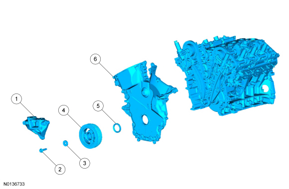
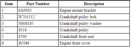
Engine Front
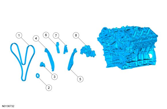
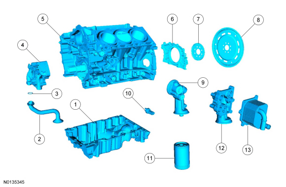
Timing Drive Components
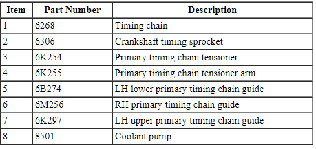
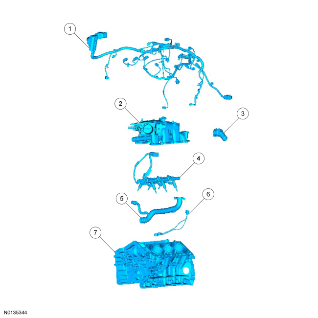
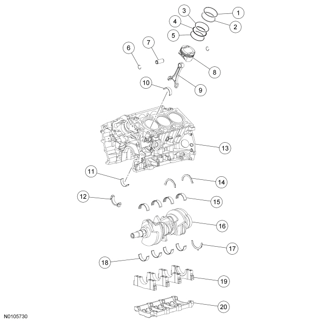
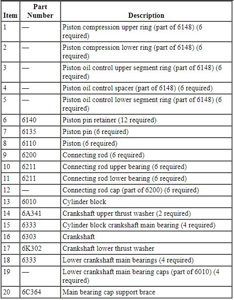
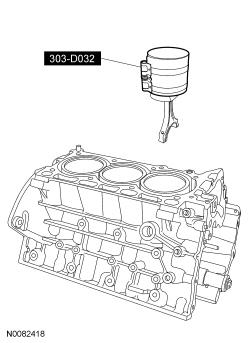
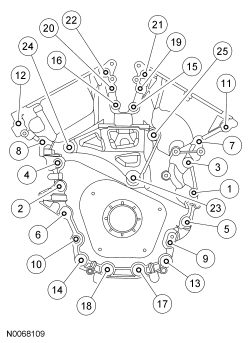
Lower Engine Block (View 1)
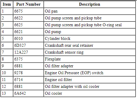
Lower Engine Block (View 2)
NOTICE: During engine repair procedures, cleanliness is extremely important. Any foreign material, including any material created while cleaning gasket surfaces that enters the oil passages, coolant passages or the oil pan, may cause engine failure.
NOTICE: Whenever turbocharger air intake system components are removed, always cover open ports to protect from debris. It is important that no foreign material enter the system. The turbocharger compressor vanes are susceptible to damage from even small particles. All components should be inspected and cleaned, if necessary, prior to installation or reassembly.
NOTE: Assembly of the engine requires various inspections/measurements of the engine components (engine block, crankshaft, connecting rods, pistons and piston rings). These inspections/measurements will aid in determining if the engine components will require replacement. For additional information, refer to Section 303-00.
- NOTE: This procedure is for selecting bearings using a new
crankshaft.
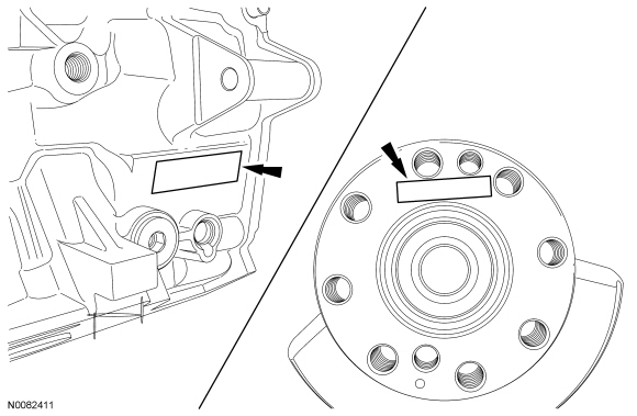
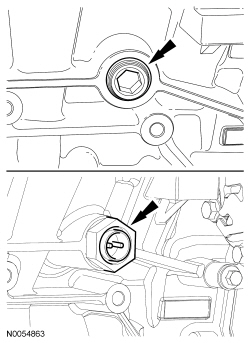
Select the crankshaft main bearings for each crankshaft journal.
- Read the code on the crankshaft flange.
- Read the code on the cylinder block face.
- The first letter after the first asterisk makes up the code for main No. 1 and the next letter for main No. 2. The first letter after the second asterisk makes up the code for main No. 3 and the last letter for main No. 4.
- NOTE: This chart is for selecting main bearings 1 and 4 only, the
remaining bearings will be selected using a different chart in the next
step.
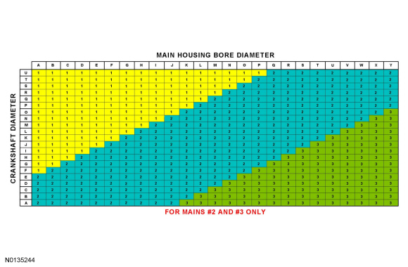
Using the data recorded earlier and the Bearing Select Fit Chart, Standard Bearings, determine the required bearing grade for main bearings 1 and 4.
- Read the first letter of the engine block main bearing code and the first letter of the crankshaft main bearing code.
- Read down the column below the engine block main bearing code letter and across the row next to the crankshaft main bearing code letter, until the 2 intersect. This is the required bearing grade(s) for the No. 1 crankshaft main bearing.
- As an example, if the engine block code letter is "F" and the crankshaft code letter is "P", the correct bearing grade for this main bearing is a "1" for the upper bearing and a "2" for the lower bearing.
- Repeat the above steps using the fourth letter of the block and crankshaft codes to select the No. 4 bearing.

- NOTE: This chart is for selecting main bearings 2 and 3 only.
Using the data recorded earlier and the Bearing Select Fit Chart, Standard Bearings, determine the required bearing grade for main bearings 2 and 3.
- Read the second letter of the engine block main bearing code and the second letter of the crankshaft main bearing code.
- Read down the column below the engine block main bearing code letter and across the row next to the crankshaft main bearing code letter, until the 2 intersect. This is the required bearing grade for the No. 2 crankshaft main bearing.
- As an example, if the engine block code letter is "F" and the crankshaft code letter is "P", the correct bearing grade for this main bearing is "1".
- Repeat the above steps using the third letter of the block and crankshaft codes to select the No. 3.
- NOTICE: The rod cap installation must keep the same
orientation as marked during disassembly or engine damage may occur.
Using the original connecting rod cap bolts, install the connecting rod caps and bolts.
- Tighten the bolts in 3 stages.
- Stage 1: Tighten to 23 Nm (17 lb-ft).
- Stage 2: Tighten to 43 Nm (32 lb-ft).
- Stage 3: Tighten an additional 90 degrees.
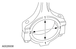
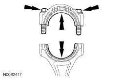
- Measure the connecting rod large end bore in 2 directions.
- Remove the bolts and the rod cap.
- Discard the connecting rod cap bolts.
- Remove the bolts and the rod cap.
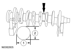
- Measure each of the crankshaft connecting rod bearing journal diameters in at least 2 directions.
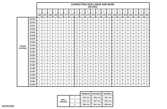
- Using the chart, select the correct connecting rod bearings for each crankshaft connecting rod journal.
- NOTE: Before assembling the cylinder block, all sealing surfaces
must be free of chips, dirt, paint and foreign material. Also, make sure the
coolant and oil passages are clear.
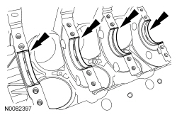
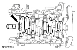
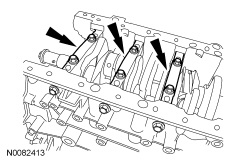
Lubricate the upper crankshaft main bearings with clean engine oil and install the 4 crankshaft main bearings in the cylinder block.
- NOTE: Do not install the upper thrust bearings until the
crankshaft is installed.
NOTE: Lubricate the thrust surfaces of the crankshaft with clean engine oil.
Install the crankshaft onto the upper main bearings.
- NOTE: Make sure the side of the thrust washer, with the wide oil
grooves, faces the crankshaft thrust surface.
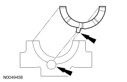
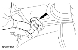
Push the crankshaft rearward and install the rear crankshaft upper thrust washer at the back of the No. 4 rear bulkhead.
- NOTE: Make sure the side of the thrust washer, with the wide oil
grooves, faces the crankshaft thrust surface.
Push the crankshaft forward and install the front crankshaft upper thrust washer at the front of the No. 4 rear bulkhead.
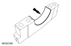
- Lubricate the crankshaft lower main bearings with clean engine oil and install them into the main bearing caps. Visually check seating and squareness of the bearings to make sure of proper seating in caps.
- Position the No. 1, No. 2 and No. 3 main bearing caps on the cylinder block and, keeping the caps as square as possible, alternately draw the caps down evenly using the new bolts until the main bearing caps are seated.
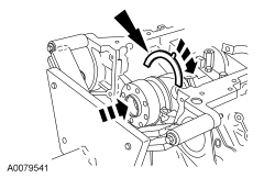
- NOTE: Make sure the side of the thrust washer, with the wide oil
grooves, faces the crankshaft thrust surface.
NOTE: To aid in assembly, apply petroleum jelly to the back of the crankshaft thrust washer.
Install the lower crankshaft thrust washer to the back side of the No. 4 rear main bearing cap, with the tab aligned with the cutout in the main bearing cap.
- Position main bearing cap No. 4 on the cylinder block and keeping the cap as square as possible, alternately draw the cap down evenly using the new bolts until the main bearing cap is seated.
- Loosen the No. 4 main bearing cap bolts.
- NOTE: While tightening the main bearing vertical bolts, push the
crankshaft forward and the No. 4 main bearing cap rearward to seat the
crankshaft thrust washers.
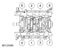
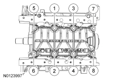
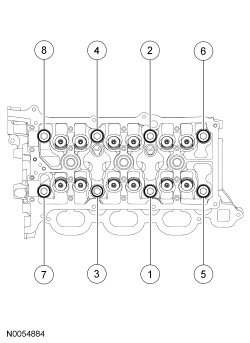
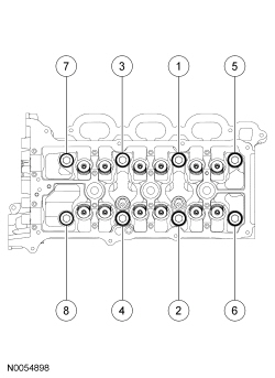
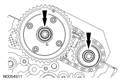
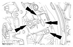
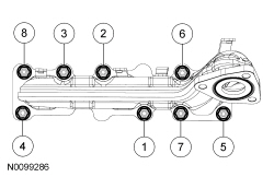
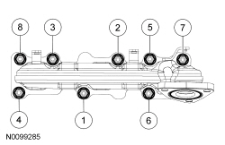
Tighten the main bearing bolts in the sequence shown in 2 stages.
- Stage 1: Tighten fasteners 1 through 8 to 33 Nm (24 lb-ft).
- Stage 2: Tighten fasteners 1 through 8 an additional 135 degrees.
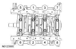
- Install the new 8 main bearing cap side bolts. Tighten in the sequence
shown in 2 stages.
- Stage 1: Tighten fasteners 1 through 8 to 45 Nm (33 lb-ft).
- Stage 2: Tighten fasteners 1 through 8 an additional 90 degrees.
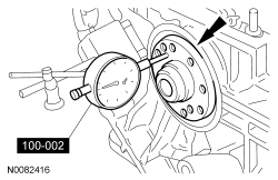
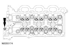
- Using the Dial Indicator Gauge with Holding Fixture, measure crankshaft
end play.
- Position the crankshaft to the rear of the cylinder block.
- Zero the Dial Indicator Gauge.
- Move the crankshaft to the front of the cylinder block. Note and record the crankshaft end play.
- NOTICE: The rod cap installation must keep the same
orientation as marked during disassembly or engine damage may occur.
Prepare the connecting rod and cap.
- Insert the new bolts in the rod cap.
- Insert the upper and lower rod bearings into the rod and cap.
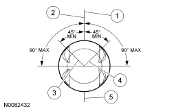
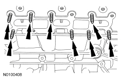
- Before installing the pistons into the cylinder block, verify proper
ring gap location.
- Center line of the piston parallel to the wrist pin bore
- Upper compression ring gap location
- Upper oil control segment ring gap location
- Lower oil control segment ring gap location
- Expander ring and lower compression ring gap location
- NOTICE: Be sure not to scratch the cylinder wall or crankshaft
journal with the connecting rod. Push the piston down until the connecting
rod bearing seats on the crankshaft journal.
NOTE: The next 3 steps are for all 6 connecting rods, rod caps and pistons. Only 1 connecting rod, rod cap and piston is shown.
NOTE: Lubricate the pistons, piston rings, connecting rod bearings and the entire cylinder bores with clean engine oil.
NOTE: Make sure the piston rings are positioned to specifications for installation. For additional information, refer to Disassembly and Assembly of Subassemblies - Piston in this section.
NOTE: If the piston and or connecting rod are being installed new, the piston rod orientation marks and the arrow on the top of the dome of the piston should be facing toward the front of the engine block.
NOTE: If the piston and connecting rod are to be reinstalled, they must be installed in the same orientation as disassembled.
Using the Piston Ring Compressor, install the piston and connecting rod assemblies.
- Seat the connecting rod on the crankshaft journal.
- NOTICE: The rod cap installation must keep the same
orientation as marked during disassembly or engine damage may occur.
NOTE: After installation of each piston, connecting rod, rod cap and bolts, rotate the crankshaft to verify smooth operation.
Install the connecting rod cap and bolts.- Tighten the bolts in 3 stages.
- Stage 1: Tighten to 23 Nm (17 lb-ft).
- Stage 2: Tighten to 43 Nm (32 lb-ft).
- Stage 3: Tighten an additional 90 degrees.
- Repeat the previous 3 steps until all 6 piston, connecting rod and connecting rod cap assemblies are installed.
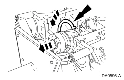
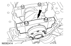
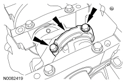
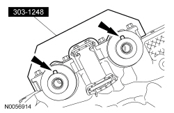
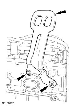
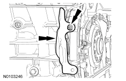
- Install the main bearing cap support brace and the new bolts. Tighten in
the sequence shown in 2 steps.
- Stage 1: Tighten fasteners to 24 Nm (18 lb-ft).
- Stage 2: Tighten fasteners an additional 180 degrees.
- NOTICE: Failure to use Motorcraft High Performance Engine RTV
Silicone may cause the engine oil to foam excessively and result in serious
engine damage.
NOTE: The crankshaft rear seal retainer must be installed and the bolts tightened within 4 minutes of sealant application.
NOTE: The stamped steel crankshaft rear seal retainer plate comes with the crankshaft rear seal.
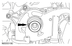
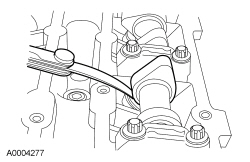
Apply a 3 mm (0.11 in) bead of Motorcraft High Performance Engine RTV Silicone to the sealing surface of the crankshaft rear seal retainer.
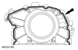
- NOTE: Lubricate the crankshaft rear seal with clean engine oil.
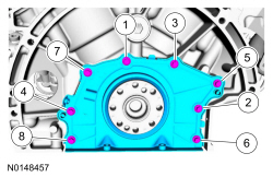
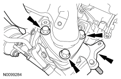
Install the crankshaft rear seal retainer and the 8 bolts.
- Tighten in the sequence shown to 10 Nm (89 lb-in).
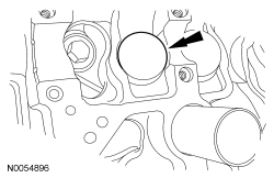
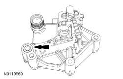
- Install the oil pump and the 3 bolts.
- Tighten to 10 Nm (89 lb-in).
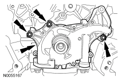
- Using a new O-ring seal, install the oil pump screen and pickup tube and
the 2 bolts.
- Tighten to 10 Nm (89 lb-in).
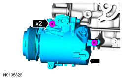
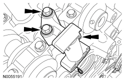
- NOTE: The A/C compressor must be installed on the cylinder block
and the 2 bolts tightened prior to installing the oil pan.
NOTE: The rear A/C compressor stud bolt was removed in engine removal.
Install the A/C compressor and the 2 stud bolts.- Tighten to 25 Nm (18 lb-ft).
- NOTICE: Failure to use Motorcraft High Performance Engine RTV
Silicone may cause the engine oil to foam excessively and result in serious
engine damage.
NOTE: The oil pan and the 4 specified bolts must be installed and the oil pan aligned to the cylinder block and A/C compressor within 4 minutes of sealant application. Final tightening of the oil pan bolts must be carried out within 60 minutes of sealant application.
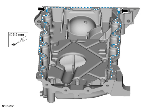
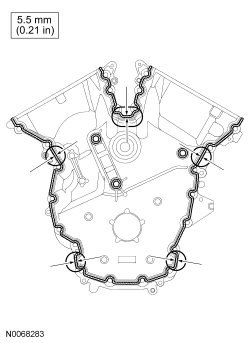
Apply a 3 mm (0.11 in) bead of Motorcraft High Performance Engine RTV Silicone to the sealing surface of the oil pan.

- Apply a 5.5 mm (0.21 in) bead of Motorcraft High Performance Engine RTV Silicone to the 2 crankshaft seal retainer plate-to-cylinder block joint areas on the sealing surface of the oil pan.
- NOTE: The oil pan and the 4 specified bolts must be installed
within 4 minutes of the start of sealant application.
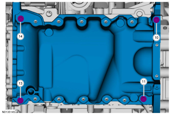
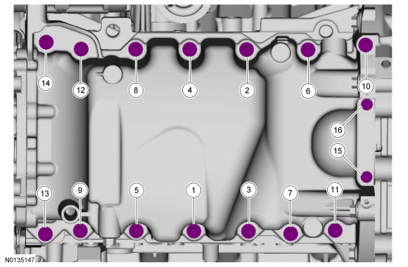
Install the oil pan and bolts 10, 11, 13 and 14.
- Tighten the bolts in the sequence shown to 3 Nm (27 lb-in).
- Loosen the bolts 180 degrees.
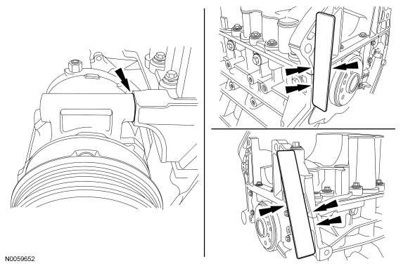
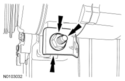
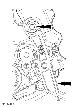
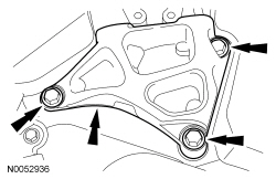
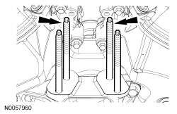
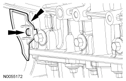
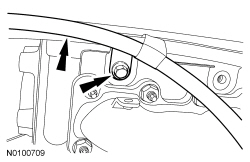
- Align the oil pan to the cylinder block and A/C compressor.
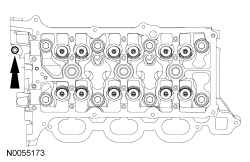
- Position the oil pan so the mounting boss is against the A/C compressor and using a straightedge, align the oil pan flush with the rear of the cylinder block at the 2 areas shown.
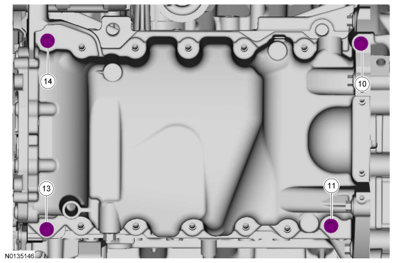
- Tighten bolts 10, 11, 13 and 14 in the sequence shown to 3 Nm (27 lb-in).
- Install the remaining oil pan bolts. Tighten all the oil pan bolts in
the sequence shown.
- Tighten the large bolts (1-14) to 24 Nm (18 lb-ft).
- Tighten the small bolts (15 and 16) to 10 Nm (89 lb-in).
- Install the A/C compressor mounting stud, Catalyst Monitor Sensor (CMS)
electrical connector bracket and nut.
- Tighten the stud to 9 Nm (80 lb-in) and the nut to 25 Nm (18 lb-ft).
- NOTE: This stud bolt will be reinstalled during engine
installation.
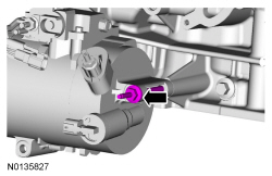
Remove the rear A/C compressor stud bolt.
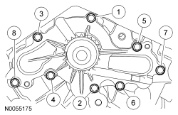
- Install the coolant pump and the 8 bolts. Tighten in the sequence shown
in 2 stages:
- Stage 1: Tighten to 10 Nm (89 lb-in).
- Stage 2: Tighten an additional 45 degrees.
- Install the Knock Sensor (KS) and the 2 bolts.
- Tighten to 20 Nm (177 lb-in).
- NOTE: Apply clean engine coolant to the O-ring seal prior to
installation.
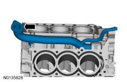
Using new O-ring seal, install the coolant inlet tube.
- Install a new gasket, the RH cylinder head and 8 new bolts. Tighten in
the sequence shown in 5 stages:
- Stage 1: Tighten to 20 Nm (177 lb-in).
- Stage 2: Tighten to 35 Nm (26 lb-ft).
- Stage 3: Tighten 90 degrees.
- Stage 4: Tighten 90 degrees.
- Stage 5: Tighten 45 degrees.
- Install the M6 bolt.
- Tighten to 10 Nm (89 lb-in).
- Install a new gasket, the LH cylinder head and 8 new bolts. Tighten in
the sequence shown in 5 stages:
- Stage 1: Tighten to 20 Nm (177 lb-in).
- Stage 2: Tighten to 35 Nm (26 lb-ft).
- Stage 3: Tighten 90 degrees.
- Stage 4: Tighten 90 degrees.
- Stage 5: Tighten 45 degrees.
- Install the M6 bolt.
- Tighten to 10 Nm (89 lb-in).
- NOTICE: The crankshaft must remain in the freewheeling
position (crankshaft dowel pin at 9 o'clock) until after the camshafts are
installed and the valve clearance is checked/adjusted. Do not turn the
crankshaft until instructed to do so. Failure to follow this process will
result in severe engine damage.
Position the crankshaft dowel pin in the 9 o'clock position.
- NOTE: The valve tappets must be installed in their original
positions.
NOTE: Coat the valve tappets with clean engine oil prior to installation.
NOTE: LH shown, RH similar.
Install the valve tappets.
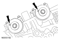
- NOTICE: The camshafts must remain in the neutral position
during installation or engine damage may occur.
NOTE: Coat the camshafts with clean engine oil prior to installation.
Position the camshafts onto the RH cylinder head in the neutral position as shown.
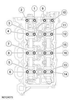
- NOTE: Cylinder head camshaft bearing caps are numbered to verify
that they are assembled in their original positions.
Install the 8 camshaft caps and the 16 bolts. Tighten the bolts in the sequence shown in the following stages:
- Stage 1: Tighten bolts 1, 2, 3 and 4 to 8 Nm (71 lb-in) then an additional 45 degrees.
- Stage 2: Tighten bolts 5 and 6 to 8 Nm (71 lb-in).
- Stage 3: Tighten bolts 7 and 8 to 8 Nm (71 lb-in) then an additional 45 degrees.
- Stage 4: Loosen bolts 5 and 6.
- Tighten bolts 5 and 6 to 8 Nm (71 lb-in) then an additional 45 degrees.
- Stage 5: Tighten bolts 9, 10, 11 and 12 to 8 Nm (71 lb-in) then an additional 45 degrees.
- Stage 6: Tighten bolts 13 and 14 to 8 Nm (71 lb-in).
- Stage 7: Tighten bolts 15 and 16 to 8 Nm (71 lb-in) then an additional 45 degrees.
- Stage 8: Loosen bolts 13 and 14.
- Tighten bolts 13 and 14 to 8 Nm (71 lb-in) then an additional 45 degrees.
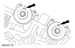
- NOTICE: The camshafts must remain in the neutral position
during installation or engine damage may occur.
NOTE: Coat the camshafts with clean engine oil prior to installation.
Position the camshafts onto the LH cylinder head in the neutral position as shown.
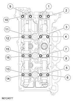
- NOTE: Cylinder head camshaft bearing caps are numbered to verify
that they are assembled in their original positions.
Install the 8 camshaft caps and the 16 bolts. Tighten the bolts in the sequence shown in the following stages:
- Stage 1: Tighten bolts 1, 2, 3 and 4 to 8 Nm (71 lb-in) then an additional 45 degrees.
- Stage 2: Tighten bolts 5 and 6 to 8 Nm (71 lb-in).
- Stage 3: Tighten bolts 7 and 8 to 8 Nm (71 lb-in) then an additional 45 degrees.
- Stage 4: Loosen bolts 5 and 6.
- Tighten bolts 5 and 6 to 8 Nm (71 lb-in) then an additional 45 degrees.
- Stage 5: Tighten bolts 9, 10, 11 and 12 to 8 Nm (71 lb-in) then an additional 45 degrees.
- Stage 6: Tighten bolts 13 and 14 to 8 Nm (71 lb-in).
- Stage 7: Tighten bolts 15 and 16 to 8 Nm (71 lb-in) then an additional 45 degrees.
- Stage 8: Loosen bolts 13 and 14.
- Tighten bolts 13 and 14 to 8 Nm (71 lb-in) then an additional 45 degrees.
- NOTICE: If any components are installed new, the engine valve
clearance must be checked/adjusted or engine damage may occur.
NOTE: Use a camshaft sprocket bolt to turn the camshafts.
Using a feeler gauge, confirm that the valve tappet clearances are within specification. For additional information, refer to Valve Clearance Check in this section.
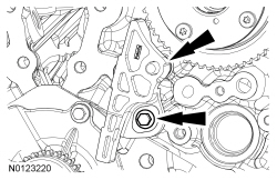
- Install the RH timing chain guide and bolt.
- Tighten to 10 Nm (89 lb-in).
- Install the RH secondary timing chain tensioner and the 2 bolts.
- Tighten to 10 Nm (89 lb-in).
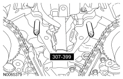
- NOTE: Use a camshaft sprocket bolt to turn the camshafts.
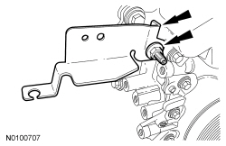
Rotate the RH camshafts to the Top Dead Center (TDC) position and install the Camshaft Holding Tool on the flats of the camshafts.
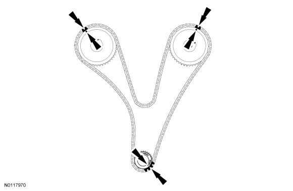
- Assemble the RH Variable Camshaft Timing (VCT) assembly, the RH exhaust
camshaft sprocket and the RH secondary timing chain.
- Align the colored links with the timing marks.
- Position the RH secondary timing assembly onto the camshafts.
- Install the new VCT bolt and the exhaust camshaft bolt and the original
washer. Tighten in 4 stages.
- Stage 1: Tighten to 40 Nm (30 lb-ft).
- Stage 2: Loosen one full turn.
- Stage 3: Tighten to 10 Nm (89 lb-in).
- Stage 4: Tighten 90 degrees.
- Remove the lockpin from the RH secondary timing chain tensioner.
- Install the LH secondary timing chain tensioner and the 2 bolts.
- Tighten to 10 Nm (89 lb-in).
- NOTE: Use a camshaft sprocket bolt to turn the camshafts.
Rotate the LH camshafts to the TDC position and install the Camshaft Holding Tool on the flats of the camshafts.
- Assemble the LH VCT assembly, the LH exhaust camshaft sprocket and the
LH secondary timing chain.
- Align the colored links with the timing marks.
- Position the LH secondary timing assembly onto the camshafts.
- Install the new VCT bolt and the exhaust camshaft bolt and the original
washer. Tighten in 4 stages.
- Stage 1: Tighten to 40 Nm (30 lb-ft).
- Stage 2: Loosen one full turn.
- Stage 3: Tighten to 10 Nm (89 lb-in).
- Stage 4: Tighten 90 degrees.
- Remove the lockpin from the LH secondary timing chain tensioner.
- Rotate the crankshaft clockwise 60 degrees to the TDC position (crankshaft dowel pin at 11 o'clock).
- Install the crankshaft timing chain sprocket.
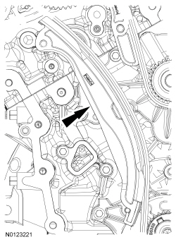
- Install the upper LH primary timing chain guide and the bolt.
- Tighten to 10 Nm (89 lb-in).
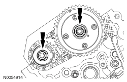
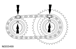
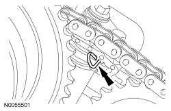
- NOTE: The crankshaft sprocket timing mark should be between the 2
colored links.
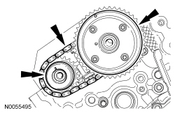
Install the primary timing chain with the colored links aligned with the timing marks on the VCT assemblies and the crankshaft sprocket.
- Install the lower LH primary timing chain guide and the 2 bolts.
- Tighten to 10 Nm (89 lb-in).
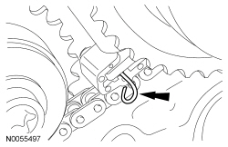
- Install the primary timing chain tensioner arm.
- Reset the primary timing chain tensioner.
- Release the ratchet detent.
- Using a soft-jawed vise, compress the ratchet plunger.
- Align the hole in the ratchet plunger with the hole in the tensioner housing and install a suitable lockpin.
- NOTE: It may be necessary to rotate the crankshaft slightly to
remove slack from the timing chain and install the tensioner.
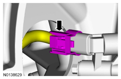
Install the primary tensioner and the 2 bolts.
- Tighten to 10 Nm (89 lb-in).
- Remove the lockpin.
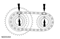
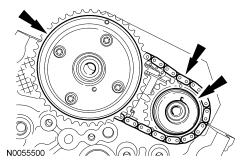
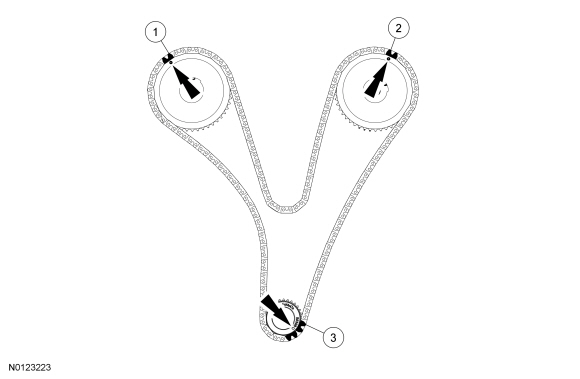
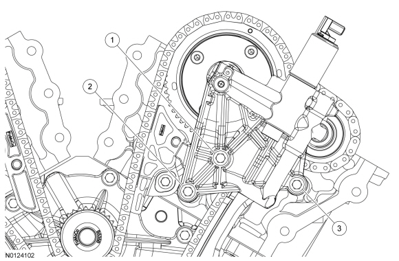
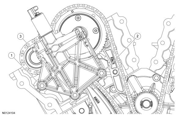
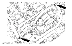
- As a post-check, verify correct alignment of all timing marks.
- There are 48 links between the RH intake VCT assembly colored link (1) and the LH intake VCT assembly colored link (2).
- There are 35 links between the LH intake VCT assembly colored link (2) and the 2 crankshaft sprocket colored links (3).
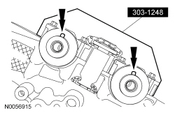
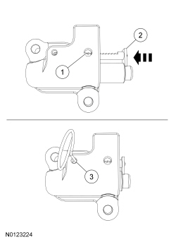
- Inspect the VCT housing seals for damage and replace as necessary.
- NOTE: RH shown, LH similar.
NOTE: During removal, the O-ring seal may remain on the cylinder head. If so, remove the O-ring seal from the cylinder head, inspect the seal (replace as necessary) and install the O-ring seal on the VCT housing.
Inspect the VCT housing-to-cylinder head O-ring seals for damage and replace as necessary.
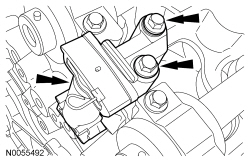
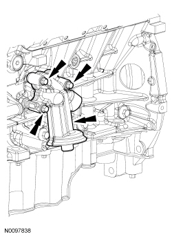
- NOTICE: Make sure the dowels on the Variable Camshaft Timing
(VCT) housing are fully engaged in the cylinder head prior to tightening the
bolts. Failure to follow this instruction will result in severe engine
damage.
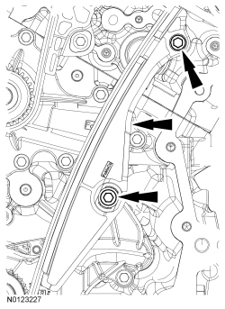
Install the LH VCT housing and the 3 bolts.
- Tighten in the sequence shown to 10 Nm (89 lb-in).
- NOTICE: Make sure the dowels on the Variable Camshaft Timing
(VCT) housing are fully engaged in the cylinder head prior to tightening the
bolts. Failure to follow this instruction will result in severe engine
damage.
Install the RH VCT housing and the 3 bolts.
- Tighten in the sequence shown to 10 Nm (89 lb-in).
- Install the Alignment Pins.
- NOTICE: Failure to use Motorcraft High Performance Engine RTV
Silicone may cause the engine oil to foam excessively and result in serious
engine damage.
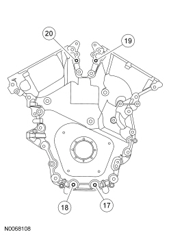
NOTE: The engine front cover and bolts 17, 18, 19 and 20 must be installed within 4 minutes of the initial sealant application. The remainder of the engine front cover bolts and the engine mount bracket bolts must be installed and tightened within 35 minutes of the initial sealant application. If the time limits are exceeded, the sealant must be removed, the sealing area cleaned and sealant reapplied. To clean the sealing area, use silicone gasket remover and metal surface prep. Failure to follow these instructions can cause future oil leakage.
Apply a 3.0 mm (0.11 in) bead of Motorcraft High Performance Engine RTV Silicone to the engine front cover sealing surfaces including the 3 engine mount bracket bosses.- Apply a 5.5 mm (0.21 in) bead of Motorcraft High Performance Engine RTV Silicone to the oil pan-to-cylinder block joint and the cylinder head-to-cylinder block joint areas of the engine front cover in 5 places as indicated.
- NOTE: Make sure the 2 locating dowel pins are seated correctly in
the cylinder block.
Install the engine front cover and bolts 17, 18, 19 and 20.
- Tighten in sequence to 3 Nm (27 lb-in).
- Remove the Alignment Pins.
- NOTE: Do not tighten the bolts at this time.
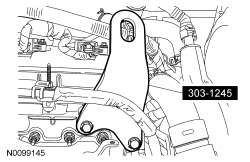
Install the engine mount bracket and the 3 bolts.
- NOTICE: Do not expose the Motorcraft High Performance Engine
RTV Silicone to engine oil for at least 90 minutes after installing the
engine front cover. Failure to follow this instruction may cause oil
leakage.
Install the remaining engine front cover bolts. Tighten all of the engine front cover bolts and engine mount bracket bolts in the sequence shown in 2 stages:
- Stage 1: Tighten bolts 1 thru 22 to 10 Nm (89 lb-in) and bolts 23, 24 and 25 to 15 Nm (133 lb-in).
- Stage 2: Tighten bolts 1 thru 22 to 24 Nm (18 lb-ft) and bolts 23, 24 and 25 to 75 Nm (55 lb-ft).
- NOTICE: The thread sealer on the engine mount studs (including
new engine mount studs if applicable) must be cleaned off with a wire brush
and new Threadlock and Sealer applied prior to installing the engine mount
studs. Failure to follow this procedure may result in damage to the engine
mount studs or engine.
Install the engine mount studs in the following sequence.
- Clean the front cover engine mount stud holes with pressurized air to remove any foreign material.
- Clean all the thread sealer from the engine mount studs (old and new studs).
- Apply new Threadlock and Sealer to the engine mount stud threads.
- Install the 2 engine mount studs.
- Tighten to 20 Nm (177 lb-in).
- Install the Heated Oxygen Sensor (HO2S) connector bracket and bolt to
the engine front cover.
- Tighten to 10 Nm (89 lb-in).
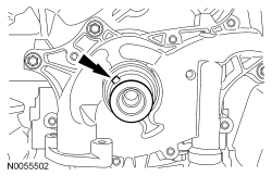
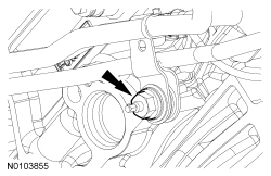
- NOTE: Apply clean engine oil to the crankshaft front seal bore in
the engine front cover.
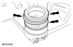
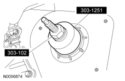
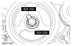
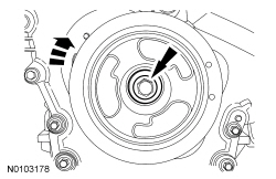
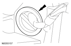
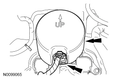
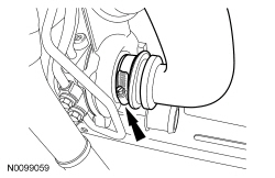
Using the Crankshaft Vibration Damper Installer and Front Crankshaft Seal Installer, install a new crankshaft front seal.
- NOTE: Lubricate the outside diameter sealing surfaces with clean
engine oil.
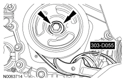
Using the Crankshaft Vibration Damper Installer and Front Cover Oil Seal Installer, install the crankshaft pulley.
- Using the Strap Wrench, install the crankshaft pulley washer and new
bolt and tighten in 4 stages.
- Stage 1: Tighten to 120 Nm (89 lb-ft).
- Stage 2: Loosen one full turn.
- Stage 3: Tighten to 50 Nm (37 lb-ft).
- Stage 4: Tighten an additional 90 degrees.
- NOTE: Installation of new seals is only required if damaged seals
were removed during disassembly of the engine.
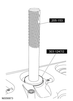
NOTE: Spark plug tube seal installation shown, VCT solenoid seal installation similar.
Using the VCT Spark Plug Tube Seal Installer and Handle, install new VCT solenoid and/or spark plug tube seals.
- NOTICE: Failure to use Motorcraft High Performance Engine RTV
Silicone may cause the engine oil to foam excessively and result in serious
engine damage.
NOTE: If the valve cover is not installed and the fasteners tightened within 4 minutes, the sealant must be removed and the sealing area cleaned. To clean the sealing area, use silicone gasket remover and metal surface prep. Failure to follow these instructions can cause future oil leakage.
Apply an 8 mm (0.31 in) bead of Motorcraft High Performance Engine RTV Silicone to the engine front cover-to-RH cylinder head joints.
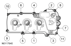
- Using a new gasket, install the RH valve cover and tighten the 11 stud
bolts.
- Tighten in the sequence shown to 10 Nm (89 lb-in).
- NOTICE: Failure to use Motorcraft High Performance Engine RTV
Silicone may cause the engine oil to foam excessively and result in serious
engine damage.
NOTE: If the valve cover is not installed and the fasteners tightened within 4 minutes, the sealant must be removed and the sealing area cleaned. To clean the sealing area, use silicone gasket remover and metal surface prep. Failure to follow these instructions can cause future oil leakage.
Apply an 8 mm (0.31 in) bead of Motorcraft High Performance Engine RTV Silicone to the engine front cover-to-LH cylinder head joints.
- Using a new gasket, install the LH valve cover and tighten the 10 stud
bolts.
- Tighten in the sequence shown to 10 Nm (89 lb-in).

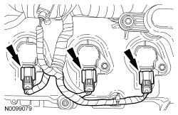
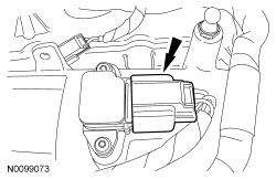
- Install the 3 LH ignition coil-on-plugs and the 3 bolts.
- Tighten to 7 Nm (62 lb-in).
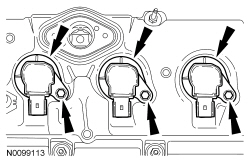
- Install the 3 RH ignition coil-on-plugs and the 3 bolts.
- Tighten to 7 Nm (62 lb-in).
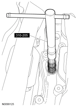
- NOTE: Make sure to thoroughly clean any residual fuel or foreign
material from the cylinder head, block and the general surrounding area of
the fuel rails and injectors.
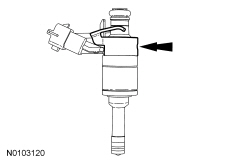
Using the Fuel Injector Brush, clean the fuel injector orifices.
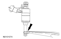
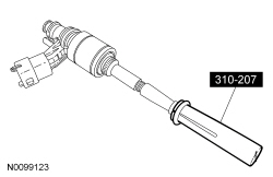
- NOTICE: Do not attempt to cut the lower Teflon seal without
first pulling it away from the fuel injector or damage to the injector may
occur.
NOTE: Be very careful when removing the lower Teflon seals, not to scratch, nick or gouge the fuel injectors.
Pull the Teflon seal away from the injector with narrow tip pliers.
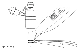
- Carefully cut and remove the 6 lower fuel injector Teflon seals.
- Discard the 6 lower fuel injector Teflon seals.
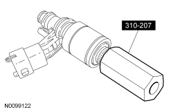
- NOTE: Do not lubricate the 6 new lower Teflon fuel injector
seals.
NOTE: The original lower Teflon fuel injector seals may be either black or white. When installing new seals, always use the black Teflon fuel injector seals.
Install the new Teflon seals on the narrow end of the Arbor (part of the Fuel Injector Seal Installer), then install the Arbor on the fuel injector tips.
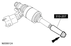
- Using the Pusher Tool (part of the Fuel Injector Seal Installer), slide the Teflon seals off of the Arbor and into the groove on the fuel injectors.
- Place the Adjustment Ring (part of the Fuel Injector Seal Installer)
beveled side first, over the fuel injector tip until it bottoms out against
the fuel injector and turn 180 degrees.
- After one minute, turn the Adjustment Ring back 180 degrees and remove.
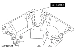
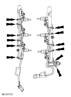
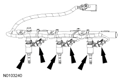
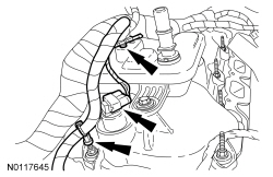
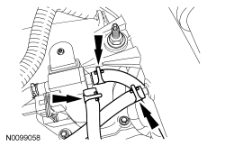
- NOTICE: It is very important to note the routing of the fuel
charge wiring harnesses on the fuel rails and index-mark the location of the
tie straps prior to removal or damage may occur to the wire harnesses during
installation. The illustration details the correct fuel charge wire harness
routing and tie strap positioning for installation.
Install the fuel charge wire harnesses and tie straps to the index-marked locations on the fuel rails. Start by attaching the first tie strap farthest down the wire harness and continue to the connector end of the harness, leaving ample slack between the fuel injectors.
- NOTICE: Use fuel injector O-ring seals that are made of
special fuel-resistant material. The use of ordinary O-ring seals may cause
the fuel system to leak. Do not reuse the O-ring seals.
NOTE: To install, apply clean engine oil to the 6 new upper fuel injector O-ring seals only. Do not lubricate the lower fuel injector Teflon seals.
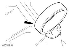
NOTE: Inspect the fuel injector support disks and replace if necessary.
Install the 6 new upper fuel injector O-ring seals.
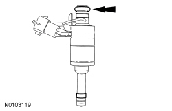
- Install the 6 new fuel injector clips.
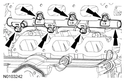
- NOTE: RH shown, LH similar.
NOTE: The anti rotation device on the fuel injector has to slip into the groove of the fuel rail cup.
Install the 6 fuel injectors into the fuel rails and connect the 6 electrical connectors.
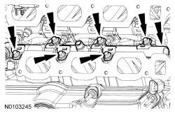
- NOTICE: It is very important to visually inspect the routing
of the wire harness to make sure that the wire harness will not be pinched
or damaged between the fuel rail and the cylinder head during installation.
Install the 6 bolts and the RH fuel rail assembly.
- Push down on the fuel rail face above the injectors and begin tightening the outer bolts first and then proceed inward.
- To install, tighten to 10 Nm (89 lb-in).
- Tighten an additional 45 degrees.
- NOTICE: It is very important to visually inspect the routing
of the wire harness to make sure that the wire harness will not be pinched
and damaged between the fuel rail and the cylinder head during installation.
Install the 6 bolts and the LH fuel rail assembly.
- Push down on the fuel rail face above the injectors and begin tightening the outer bolts first and proceed inward.
- To install, tighten to 10 Nm (89 lb-in).
- Tighten an additional 45 degrees.
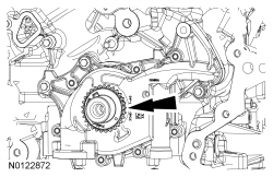
- NOTE: The cam lobe for the fuel injection pump must be at Bottom
Dead Center (BDC) for the fuel injection pump installation.
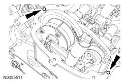
Using the crankshaft pulley bolt, turn the crankshaft until the fuel injection pump cam lobe is at BDC.
- NOTE: Valve cover is removed for clarity.
NOTE: Apply clean engine oil to the fuel injection pump mounting pedestal bore.
Install the fuel injection pump roller tappet.
- NOTE: Apply clean engine oil to the fuel injection pump mounting
plate seal.
Inspect the fuel injection pump mounting plate-to-valve cover gasket and replace if necessary.
- NOTE: Apply clean engine oil to the fuel injection pump mounting
plate O-ring seals.
Inspect the 2 fuel injection pump mounting plate O-ring seals and replace if necessary.
- NOTE: Apply clean engine oil to the fuel injection pump O-ring
seal.
Install the fuel injection pump on the fuel injection pump mounting plate.
- NOTE: Clean the fuel injection pump bolts and apply Thread
Sealant with PTFE to the bolts.
Install the fuel injection pump and the 2 bolts finger-tight.
- Tighten to 10 Nm (89 lb-in).
- Tighten an additional 45 degrees.
- NOTE: To install, apply clean engine oil to the threads of the 3
high-pressure fuel tube flare nuts.
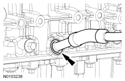
Install the high-pressure fuel tube and tighten the 3 flare nuts in the following 3 stages.
- Stage 1: Tighten to 32 Nm (24 lb-ft).
- Stage 2: Wait 10 minutes to minimize pre-stress.
- Stage 3: Tighten to 32 Nm (24 lb-ft).
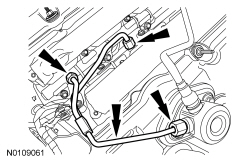
- Install the high-pressure fuel tube bracket nut.
- Tighten to 8 Nm (71 lb-in).
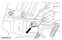
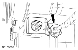
- Install the RH cylinder block drain plug or, if equipped, the block
heater.
- Tighten the cylinder block drain plug to 10 Nm (89 lb-in) plus an additional 720 degrees.
- Tighten the block heater to 40 Nm (30 lb-ft).
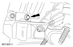
- Install the LH cylinder block drain plug.
- Tighten to 16 Nm (142 lb-in) plus an additional 180 degrees.
- Attach the wiring harness retainer to the rear of the LH cylinder head.
- Install the cover and the pin-type retainer.
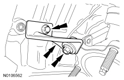
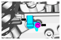
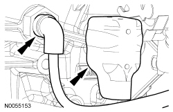
- Install the turbocharger coolant tube assembly and the bolt.
- Tighten to 10 Nm (89 lb-in).
- Install the RH engine lifting eye and the 2 bolts.
- Tighten to 24 Nm (18 lb-ft).
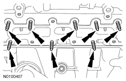
- Install 8 new RH exhaust manifold studs.
- Tighten to 12 Nm (106 lb-in).
- NOTICE: Failure to tighten the exhaust manifold nuts to
specification a second time will cause the exhaust manifold to develop an
exhaust leak.
Install a new gasket, RH exhaust manifold and 8 new nuts. Tighten in 2 stages in the sequence shown:
- Stage 1: Tighten to 15 Nm (133 lb-in).
- Stage 2: Tighten to 20 Nm (177 lb-in).
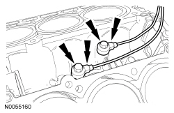
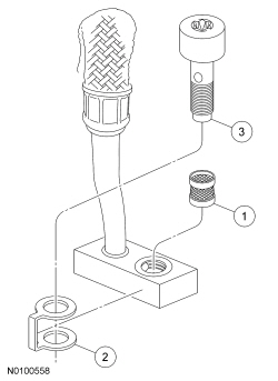
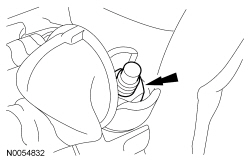
- Install the oil supply tube filter, washer and bolt.
- Install a new oil supply tube filter in the oil supply tube block.
- Slide the new washer onto the oil supply tube block.
- Install the banjo bolt into the oil supply tube block.
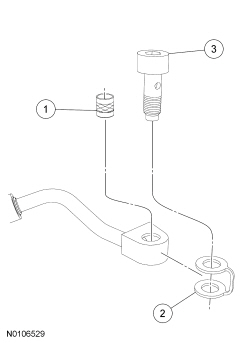
- Install the RH turbocharger oil supply tube.
- Tighten the bolt to 40 Nm (30 lb-ft).
- Install a new gasket, the turbocharger and the 3 new exhaust
manifold-to-turbocharger bolts.
- Tighten to 45 Nm (33 lb-ft).
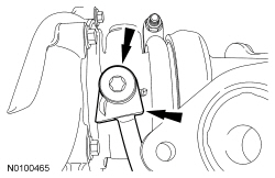
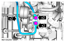
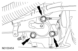
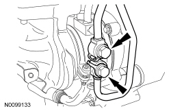
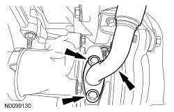
- Install the upper RH turbocharger-to-cylinder block bracket and the 3
bolts and position the bracket as far clockwise as possible and tighten the
bolts in the following sequence:
- Tighten the lower bolt to 26 Nm (19 lb-ft).
- Tighten the upper bolt to 26 Nm (19 lb-ft).
- Tighten the turbocharger bolt to 19 Nm (168 lb-in).
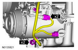
- Using 2 new sealing washers, install the 2 RH turbocharger coolant tubes
and banjo bolts.
- Tighten to 40 Nm (30 lb-ft).
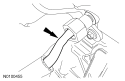
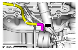
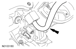
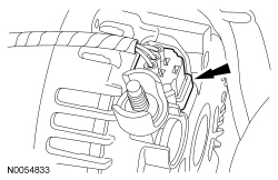
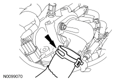
- NOTE: Listen for audible click when installing the oil supply
tube into the quick connect fitting.
Install the RH oil supply tube into the quick connect fitting.
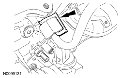
- Install the RH oil supply tube secondary latch.
- NOTE: Lubricate the cylinder block bore with clean engine oil.
Using 2 new O-ring seals, install the RH turbocharger oil return tube in the cylinder block.
- Install a new gasket and the RH turbocharger oil return tube and the 2
bolts.
- Tighten to 10 Nm (89 lb-in).
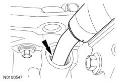
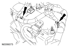
- NOTE: Make sure the turbocharger wastegate regulating valve hose
does not contact the exhaust manifold heat shield.
Connect the turbocharger wastegate regulating valve hose to the RH turbocharger assembly.
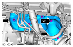
- NOTE: Make sure the heat shield does not contact the wastegate
arm.
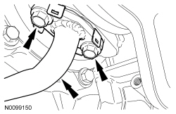
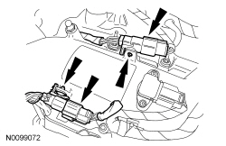
Install the 2 upper RH exhaust manifold heat shields and the 5 bolts.
- Tighten to 12 Nm (106 lb-in).
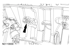
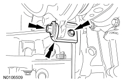
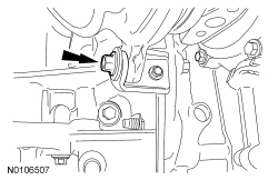
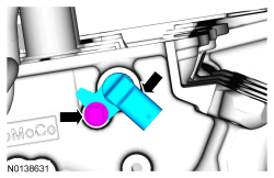
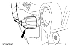
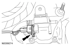
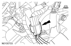
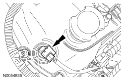
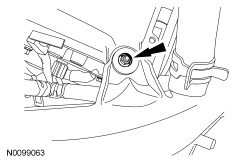
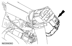
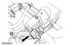
- Install the Crankshaft Position (CKP) sensor and install the bolt.
- Tighten to 10 Nm (89 lb-in).
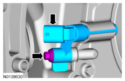
- Connect the CKP sensor electrical connector.
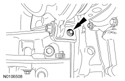
- Install the wiring harness grommet.
- Install the wiring harness retainer stud bolt.
- Tighten to 10 Nm (89 lb-in).
- Install the heat shield and the nut.
- Tighten to 10 Nm (89 lb-in).
- Install the LH turbocharger coolant tube bracket-to-cylinder head nut.
- Tighten to 10 Nm (89 lb-in).
- Install 8 new LH exhaust manifold studs.
- Tighten to 12 Nm (106 lb-in).
- NOTICE: Failure to tighten the exhaust manifold nuts to
specification a second time will cause the exhaust manifold to develop an
exhaust leak.
Install a new gasket, LH exhaust manifold and turbocharger assembly and 8 new nuts. Tighten the nuts in 2 stages in the sequence shown:
- Stage 1: Tighten to 15 Nm (133 lb-in).
- Stage 2: Tighten to 20 Nm (177 lb-in).
- Install a new gasket the LH turbocharger and the 3 new exhaust
manifold-to-turbocharger bolts.
- Tighten to 45 Nm (33 lb-ft).
- Install the oil supply tube filter, washer and bolt.
- Install a new oil supply tube filter in the oil supply tube block.
- Slide the new washer onto the oil supply tube block.
- Install the bolt into the oil supply tube block.
- Install the LH turbocharger oil supply tube.
- Tighten the bolt to 40 Nm (30 lb-ft).
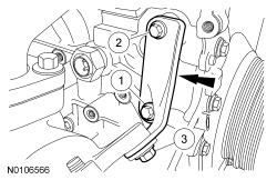
- Install the upper turbocharger bracket-to-cylinder block and the 2
bolts.
- Do not tighten the bolts at this time.
- Install the lower turbocharger-to-cylinder block bracket and the 2
bolts.
- Do not tighten the bolts at this time.
NOTICE: The next 4 steps must be performed in order or damage to the turbocharger may occur.
- Tighten the upper turbocharger bracket-to-turbocharger bolt.
- Tighten to 19 Nm (168 lb-in).
- Tighten the upper turbocharger bracket-to-cylinder block bolt.
- Tighten to 25 Nm (18 lb-ft).
- Tighten the lower turbocharger bracket-to-turbocharger bolt.
- Tighten to 19 Nm (168 lb-in).
- Tighten the lower turbocharger bracket-to-cylinder block bolt.
- Tighten to 11 Nm (97 lb-in).
- Using 2 new sealing washers, install the 2 LH turbocharger coolant tubes
and the banjo bolts.
- Tighten to 40 Nm (30 lb-ft).
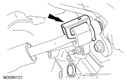
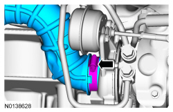
- NOTE: Listen for audible click when installing the oil supply
tube into the quick connect fitting.
Install the LH oil supply tube into the quick connect fitting.
- Install the LH oil supply tube secondary latch.
- NOTE: Lubricate the oil pan bore with clean engine oil.
Using 2 new O-ring seals, install the LH turbocharger oil return tube in the oil pan.
- Install a new gasket, turbocharger oil return tube and the 2 bolts.
- Tighten to 10 Nm (89 lb-in).
- NOTE: Make sure the turbocharger wastegate regulating valve hose
does not contact the exhaust manifold heat shield.
Connect the turbocharger wastegate regulating valve hose to the LH turbocharger assembly.
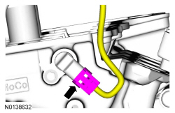
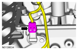
- Install LH Camshaft Position (CMP) sensor and the bolt.
- Tighten to 10 Nm (89 lb-in).
- Connect the LH CMP sensor electrical connector.
- Connect the Cylinder Head Temperature (CHT) sensor electrical connector.
- Install the RH CMP sensor and the bolt.
- Tighten to 10 Nm (89 lb-in).
- Connect the RH CMP sensor electrical connector.
- Attach all of the wiring harness retainers to the RH valve cover and stud bolts.
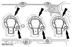
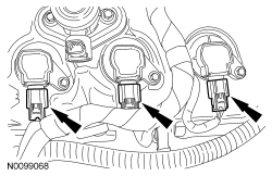
- Connect the 3 RH ignition coil-on-plug electrical connectors.
- Connect the RH VCT solenoid electrical connector and attach the 2 wiring harness retainers.
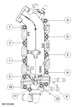
- NOTICE: If the engine is repaired or replaced because of upper
engine failure, typically including valve or piston damage, check the intake
manifold for metal debris. If metal debris is found, install a new intake
manifold. Failure to follow these instructions can result in engine damage.
NOTE: Make sure the fuel rail wiring harnesses are routed correct.
NOTE: Installing the 2 long bolts first will aid in installing the intake manifold.
Using new intake manifold, coolant crossover and thermostat housing gaskets, install the intake manifold and the 12 bolts. Tighten in the sequence shown.- Tighten to 10 Nm (89 lb-in).
- Tighten an additional 45 degrees.
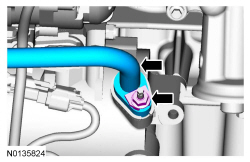
- Connect the 2 turbocharger coolant hoses to the intake manifold.
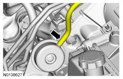
- Position the fuel tube and install the fuel tube-to-engine front cover
bracket bolt.
- Tighten to 10 Nm (89 lb-in).
- Attach the 2 wire harness-to-intake manifold retainers.
- Connect the turbocharger wastegate regulating valve electrical connector.
- Connect the Manifold Absolute Pressure (MAP)/Intake Air Temperature 2 (IAT2) sensor electrical connector.
- Connect and attach the 2 fuel injector wiring harness electrical connectors.
- Connect the KS sensor electrical connector.
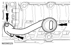
- Install the oil level indicator.
- Attach all the wiring harness retainers to the LH valve cover and stud bolts.
- Connect the 3 LH ignition coil-on-plug electrical connectors.
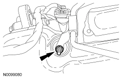
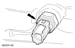
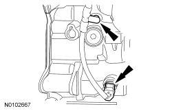
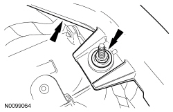
- NOTE: Apply thread sealant with PTFE to the Engine Oil Pressure
(EOP) switch threads.
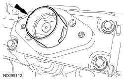
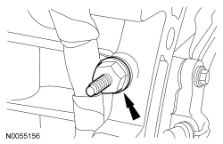
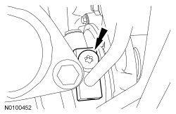
Install the EOP switch.
- To install, tighten to 14 Nm (124 lb-in) plus an additional 180 degrees.
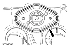
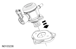
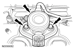
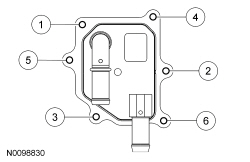
- NOTE: Engine without oil cooler shown, engine oil cooler similar.
Using a new gasket, install the oil filter adapter and the 3 bolts.
- Tighten to 10 Nm (89 lb-in) plus an additional 45 degrees.
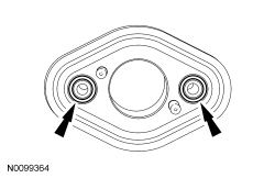
- NOTICE: A new oil cooler must be installed or severe damage to
the engine may occur.
If equipped, using new gaskets, install the oil cooler and 6 bolts. Tighten in the sequence shown.
- Tighten to 10 Nm (89 lb-in).
- Connect the EOP electrical connector.
- Attach the EOP wiring harness retainer to the engine block.
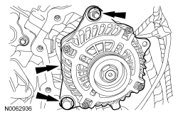
- Install the stud, generator and the nut and bolt.
- Tighten the stud to 8 Nm (71 lb-in).
- Tighten the nut and bolt to 47 Nm (35 lb-ft).
- Connect the generator electrical connector.
- Connect the generator B+ cable and install the nut.
- Tighten to 17 Nm (150 lb-in).
- Connect the A/C compressor and the pressure releif valve electrical
connectors.
- Attach the 2 wiring harness retainers from the to the A/C stud bolts.
- Attach the CMS electrical connector to the A/C compressor bracket.
- Connect the LH camshaft VCT solenoid electrical connector.
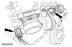
- Connect the Throttle Position (TP) sensor and electronic Throttle Body (TB) electrical connectors.
- Connect the electrical connector and install the noise insulator shield for the fuel injection pump.
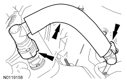
- Install the PCV tube and connect the 2 quick connect couplings. For additional information, refer to Section 310-00.
- Install the lower radiator hose to the thermostat housing.
- NOTICE: The compression limiter bushing may fall out of the
mounting bracket grommet on the Charge Air Cooler (CAC) tube during service.
Make sure the bushing is in place when reinstalling the tube or damage to
the tube may occur.
Install the RH Charge Air Cooler (CAC) tube and turbocharger intake tube as an assembly and install the RH CAC tube nut to the intake manifold.
- Tighten to 6 Nm (53 lb-in).
- NOTICE: The compression limiter bushing may fall out of the
mounting bracket grommet on the turbocharger intake tube during service.
Make sure the bushing is in place when reinstalling the tube or damage to
the tube may occur.
Install the RH turbocharger intake tube nut.
- Tighten to 6 Nm (53 lb-in).
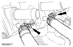
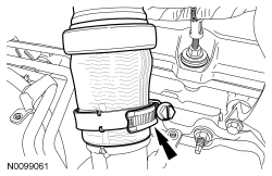
- NOTE: Align the index marks for the RH turbocharger intake pipe.
Install the RH turbocharger intake pipe to the RH turbocharger and tighten the clamp.
- Tighten to 5 Nm (44 lb-in).
- NOTE: Align the index marks for the RH CAC tube.
Install the RH CAC tube to the RH turbocharger and tighten the clamp.
- Tighten to 5 Nm (44 lb-in).
- Connect the RH turbocharger bypass valve electrical connector.
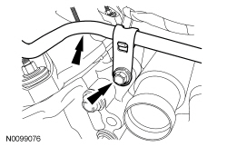
- NOTE: Align the index marks for the LH turbocharger intake tube.
Install the LH turbocharger intake tube to the LH turbocharger and tighten the clamp.
- Tighten to 5 Nm (44 lb-in).
- Install the turbocharger wastegate regulating valve hoses to the turbocharger wastegate regulating valve and to the RH CAC tube.
- Connect the LH turbocharger bypass valve electrical connector.
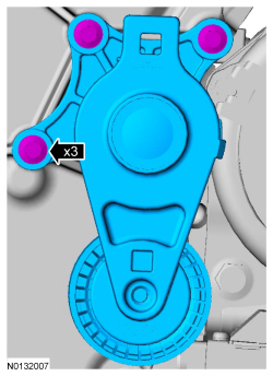
- Install the accessory drive belt tensioner and the 3 bolts.
- Tighten to 11 Nm (97 lb-in).
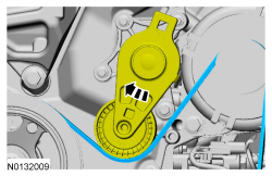
- Rotate the accessory drive belt tensioner clockwise and install the accessory drive belt.
- Using a new O-ring seal and gasket seal, connect the A/C tube to the
compressor and install the nut.
- Tighten to 15 Nm (133 lb-in).
- If equipped, connect the block heater electrical connector and install the heat shield.
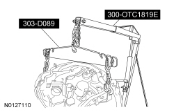
- Install the Engine Lift Eye on the LH cylinder head.
- Using the Floor Crane and Spreader Bar, remove the engine from the stand.
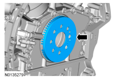
- Install the crankshaft sensor ring.
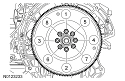
- NOTE: One of the 8 flexplate holes are offset so the flexplate
can only be installed in one position.
Install the flexplate and the 8 bolts.
- Tighten in the sequence shown to 80 Nm (59 lb-ft).
 Disassembly and Assembly of Subassemblies
Cylinder Head
Special Tool(s)
Material
Cylinder Head
NOTE: RH shown, LH similar.
Disassembly
NOTE: If the components are to be reinstalled, they must be installed
in the same positions ...
 Installation
Engine
Special Tool(s)
Material
NOTICE: Whenever turbocharger air intake system components are
removed, always cover open ports to protect from debris. It is important that no
foreign materia ...
Other materials:
Fuel Charging and Controls - 3.7L Ti-VCT
SPECIFICATIONS
Material
Torque Specifications
DESCRIPTION AND OPERATION
Fuel Charging and Controls
Component Locations
WARNING: Do
not smoke, carry lighted tobacco or have an open flame of any type when working
on or near any fuel-related component. Highly flammable mixtures are always
present ...
Cleaning the engine
Engines are more efficient when they are clean because grease and dirt
buildup keep the engine warmer than normal.
When washing:
‚ÄĘ Take care when using a power washer to clean the engine. The
high-pressure fluid could penetrate the sealed parts and cause
damage.
‚ÄĘ Do not spray a hot en ...
MyFord‚ĄĘ system
WARNING: Driving while distracted can result in loss of vehicle
control, crash and injury. We strongly recommend that you use
extreme caution when using any device that may take your focus off
the road. Your primary responsibility is the safe operation of your
vehicle. We recommend against the ...
