Wheels And Tires
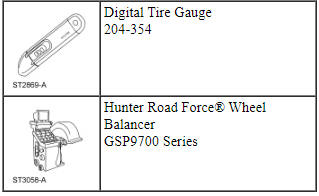
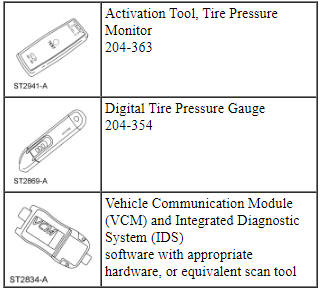
Special Tool(s)
Inspection and Verification
WARNING: Vehicle may have multiple drive wheels. Do not use engine to power the driveline unless all drive wheels are elevated off the ground. Drive wheels in contact with ground could cause unexpected vehicle movement. Failure to follow this instruction may result in serious personal injury.
Verify the customer concern by carrying out a road test on a smooth road. If any vibrations are apparent, GO to Symptom Chart - NVH.
To maximize tire performance, inspect for signs of incorrect inflation and uneven wear, which may indicate a need for balancing, rotation or front suspension alignment.
Correct tire pressure and driving techniques have an important influence on tire life. Heavy cornering, excessively rapid acceleration and unnecessary sharp braking increase tire wear.
Replacement tires must follow the recommended:
- tire sizes.
- speed rating.
- load range.
- tire construction type.
The use of any other tire/wheel size, load range or type can seriously affect:
- ride.
- handling.
- speedometer/odometer calibration.
- vehicle ground clearance.
- tire clearance between the body and chassis.
- wheel bearing life.
- braking performance.
New wheels need to be installed when the vehicle wheels:
- are bent.
- are cracked.
- are dented.
- are heavily corroded.
- are leaking.
- have elongated wheel hub bolt holes.
- have excessive lateral or radial runout.
It is mandatory to use only the tire sizes recommended on the tire label located on the driver door or door pillar attached to the vehicle. Larger or smaller tires can damage the vehicle, affect durability and require changing the speedometer calibration. Make sure wheel size and offsets match those recommended for the tire in use.
- Inspect the tires for signs of uneven wear. Refer to the following descriptions to identify the type of wear and GO to Symptom Chart - Tire Wear for the appropriate repair action to be carried out.
- Check the tires for:
- cuts.
- stone bruises.
- abrasions.
- blisters.
- embedded objects.
- Check the valve stems for:
- cracks.
- cuts.
Install a new valve stem when damage is found or anytime a new tire is installed.
- Tread wear indicators are molded into the bottom of the tread grooves. Install a new tire when the indicator bands become less than 2/32 inch.
Tire Wear
Tire wear is commonly defined as a loss of tread depth. Tire tread wear occurs due to friction with the contact surface (road/pavement). The tread should wear down uniformly all the way around the circumference of the tire and all the way across the tread face. When this does not occur, the tire may have abnormal/incorrect wear.
Normal Tire Wear
Normal tire wear is identified as even wear around and across the tread. Because there are many factors (driving style, road surfaces, type of vehicle, type of tire) that can affect tire wear, there is no absolute mileage expectation for a normal wear condition. A tire is considered worn-out when the tread has worn to the level of the tread-wear indicators.
Abnormal/Incorrect Tire Wear
Abnormal/incorrect tire wear is identified as tire wear that is not even around or across the tread and that creates performance-related issues.
Abnormal/incorrect wear can be caused by numerous factors, some of which include driving style (aggressive, passive), climate (hot, cold), road conditions, vehicle loading and maintenance (correct tire pressure, rotation intervals and balance). It is important to determine the root cause of wear on a vehicle before carrying out repair. Tires exhibiting abnormal/incorrect tire wear may still be serviceable provided that the minimum tread depth is greater than 2/32 inch and the tire is not causing a vehicle performance (noise/vibration) concern.
Some abnormal/incorrect wear patterns look the same all the way around the tread of the tire, other wear patterns are not consistent and can occur in various spots on the tread area. The underlying causes of the 6 wear categories are different. Refer to the following descriptions to identify the type of wear and GO to Symptom Chart - Tire Wear for the appropriate repair action to be carried out.
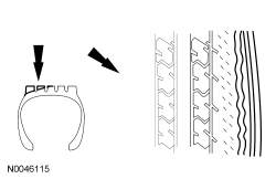
Inner Edge/Shoulder Wear
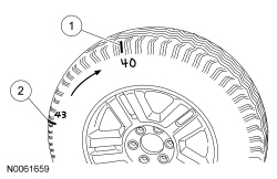
Inner edge (or shoulder) wear occurs on the inside edge of the tire and is usually caused by excessive toe out and/or excessive negative camber. If the tread depth of the outer shoulder is at least 50% greater than the tread depth of the inner shoulder, the tire is experiencing inner edge/shoulder wear. To determine whether tires have this type of wear, visually inspect the tires. In some instances, it may be necessary to measure the tread depth of each rib and compare it to that of the shoulder.
NOTE: RF tire shown, others similar.
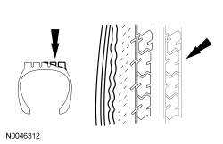
Outer Edge/Shoulder Wear
Outer edge (or shoulder) wear occurs on the outside edge of the tire and is usually caused by excessive toe in and/or excessive positive camber. If the tread depth of the inner shoulder is at least 50% greater than the tread depth of the outer shoulder, the tire is experiencing outer edge/shoulder wear. To determine whether tires have this type of wear, visually inspect the tires. In some instances, it may be necessary to measure the tread depth of each rib and compare it to that of the shoulder.
NOTE: RF tire shown, others similar.
Heel/Toe Wear
Heel/toe wear (also known as feathering) occurs along the outside or inside edge/shoulder of the tire. To determine whether tires have this type of wear, visually inspect the tires in both the inside and outside shoulder ribs. In some instances, it may be necessary to measure the difference in tread depth of leading versus trailing edge of each lug in the inside and outside shoulder rib.
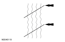
Diagonal Wear
Diagonal wear occurs diagonally across the tread area and around the circumference of the tire. To determine whether tires have this type of wear, visually inspect the tires to determine if the wear pattern runs diagonally across the tread and around the circumference of the tire. In some instances, the difference in tread depth along the diagonal wear pattern may need to be measured.
Symptom Chart - Tire Wear
NOTE: For suspension system and additional alignment diagnosis, refer to Section 204-00.
Symptom Chart - NVH
NOTE: NVH symptoms should be identified using the diagnostic tools that are available. For a list of these tools, an explanation of their uses and a glossary of common terms, refer to Section 100-04. Since it is possible any one of multiple systems may be the cause of a symptom, it may be necessary to use a process of elimination type of diagnostic approach to pinpoint the responsible system. If this is not the causal system for the symptom, refer back to Section 100-04 for the next likely system and continue diagnosis.
Pinpoint Tests
For a description of the various tire wear patterns, refer to Inspection and Verification.
Pinpoint Test A: Inner Edge/Shoulder Wear
-
This pinpoint test is intended to diagnose the following:
- Excessive toe out
- Incorrect wheel and tire rotation
PINPOINT TEST A: INNER EDGE/SHOULDER WEAR
Pinpoint Test B: Outer Edge/Shoulder Wear
-
This pinpoint test is intended to diagnose the following:
- Excessive toe in
- Incorrect wheel and tire rotation
PINPOINT TEST B: OUTER EDGE/SHOULDER WEAR

Pinpoint Test C: Diagonal Wear
-
This pinpoint test is intended to diagnose the following:
- Incorrect wheel and tire rotation
- Excessive toe in/out
- Incorrect tire inflation
- Loose, worn or damaged suspension components
PINPOINT TEST C: DIAGONAL WEAR
Component Tests
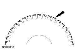
Radial Runout
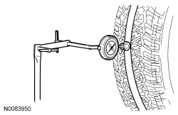
Radial runout is the egg-shaped deviation from a perfect circle and is measured perpendicular to the circumference. On a wheel and tire assembly, this means measuring the center tire tread rib. The center rib is indicative of the condition of the tire as a whole. Total runout is the difference between the maximum-to-minimum gauge reading. The high spot is the location of maximum runout.
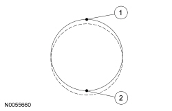
- High spot
- Low spot
Loaded Runout Measurement (Hunter Road Force 9700 Series Wheel Balancer)
NOTE: Diagnosis of tire/wheel vibration should not be performed on tires with less than 320 km (200 mi). Some initial tire/wheel vibration issues (such as flat spotting) may correct themselves after the tires have been in service for 320 km (200 mi).
This procedure is intended to assist with the diagnosis of wheel and tire assembly runout and/or force variation issues.
The Hunter Road Force 9700 Series Wheel Balancer measures the wheel and tire assembly's loaded runout and the tire's radial spring rate. The balancer then converts the runout into pounds of force (termed as Road Force). Measuring loaded runout (Road Force) is more effective than measuring unloaded runout using a dial indicator.
- Using a tire crayon, record the vehicle position on the inward sidewall of all 4 tires.
- Remove the wheel and tire assemblies. Refer to Wheel and Tire in this section.
- NOTE: Use only the Digital Tire Gauge any time tire pressures are
measured to be sure that accurate values are obtained.
Make sure that the tire pressures are set to the correct pressure as indicated on the Vehicle Certification (VC) label.
- NOTICE: Make sure that the correct wheel balancer adapters are
used when mounting the assembly to the wheel balancer or damage to the wheel
may occur.
NOTE: Make sure that the wheel and tire assembly is clean and free of foreign material prior to installation on the balancer.
NOTE: The wheel balancer inflation station must be turned OFF for tires with inflation pressures of 414 kPa (60 psi) or above.
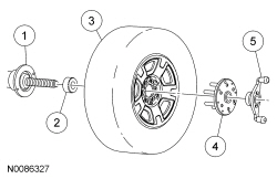
Mount the wheel and tire assembly on a suitable wheel balancer using the correct wheel balancer adapters as shown. Refer to the list of recommended wheel balancer adapters on the PTS website.

- Wheel balancer
- Cone
- Wheel and tire assembly
- Finger plate
- Balancer wing nut
- Measure the Road Force.
- Temporarily mark the high spot and the Road Force value on the sidewall of the tire. If the wheel and tire assembly Road Force value is greater than 9 kg (20 lb), carry out the Match Mounting procedure to optimize the wheel and tire assembly.
- If the wheel and tire assembly Road Force value is 9 kg (20 lb) or less, permanently mark the high spot and the Road Force value on the inward sidewall of the tire for reference during future wheel and tire service. Balance the assembly and install the wheel and tire on the vehicle using the Wheel-to-Hub Optimization procedure.
Runout Measurement (Dial Indicator)
NOTE: Diagnosis of tire/wheel vibration should not be performed on tires with less than 320 km (200 mi). Some initial tire/wheel vibration issues (such as flat spotting) will correct themselves after the tires have been in service for 320 km (200 mi).
NOTE: Loaded run-out measurements are the preferred method for verifying tire serviceability. While a dial indicator can be used to optimize the position of the tire on the wheel, the unloaded run-out measurement cannot accurately determine if the tire should be removed from service.
The following procedures should be used if normal diagnostics leads to a potential runout issue.
Some vehicles may exhibit a wheel and tire vibration caused by excessive runout. Radial runout measurements can be taken using a dial indicator and should be measured with the wheel and tire assembly mounted on a suitable wheel balancer. The dial indicator should be mounted securely to eliminate gauge movement when measuring runout.
- NOTE: Use only the Digital Tire Gauge any time tire pressures are
measured to be sure that accurate values are obtained.
Make sure that the tire pressures are set to the correct pressure as indicated on the VC label.
- Using a tire crayon, record the vehicle position on the inward sidewall of all 4 tires.
- Remove the wheel and tire assemblies. Refer to Wheel and Tire in this section.
- NOTICE: Make sure that the correct wheel balancer adapters are
used when mounting the assembly to the wheel balancer or damage to the wheel
may occur.
NOTE: Make sure that the wheel and tire assembly is clean and free of foreign material prior to installation on the balancer.
Mount the wheel and tire assembly on a suitable wheel balancer using the correct wheel balancer adapters as shown. Refer to the list of recommended wheel balancer adapters on the PTS website.
- Wheel balancer
- Cone
- Wheel and tire assembly
- Finger plate
- Balancer wing nut
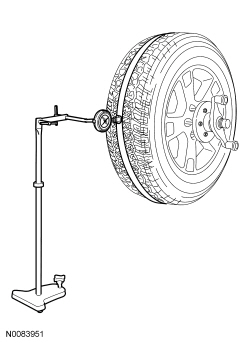
- NOTE: Masking tape can be applied on the center tread rib to
allow for a smoother measuring surface. Some fluctuation of the gauge
reading is expected. Observe the overall sweep of the gauge from the highest
to the lowest spot on the tire.
Position a suitable dial indicator and stand with the dial indicator on the center tread rib.
- Rotate the wheel and tire assembly (or wheel) to locate the low spot.
- Adjust the runout gauge to read 0.
- Rotate the wheel and tire assembly one complete revolution to make sure that the low spot has been found and that the dial indicator returns to a 0 reading.
- While slowly and constantly rotating the wheel and tire assembly (or
wheel), measure the radial runout.
- Note the variance (runout) from 0 on the dial of the gauge.
- If the runout reading of a wheel and tire assembly is greater than 1.14 mm (0.045 in), locate and temporarily mark the high spot and runout reading on the sidewall of the tire and carry out the Match Mounting procedure to optimize the wheel and tire assembly.
- If the runout reading of a wheel and tire assembly is 1.14 mm (0.045 in) or less, permanently mark the high spot and the runout reading on the inward sidewall of the tire for reference during future wheel and tire service. Balance the assembly and install the wheel and tire on the vehicle using the Wheel-to-Hub Optimization procedure.
Match Mounting
NOTE: Road Force values in illustrations are shown in pounds.
Match mounting is a technique used to reduce radial runout or road force on wheel and tire assemblies. Excessive runout is a source of ride quality complaints and match mounting can be used to minimize the runout. Match mounting can be accomplished by changing the position of the tire on the wheel.
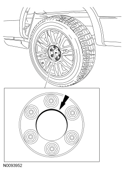
- Position the wheel and tire assembly on a tire machine and put a reference mark on the tire sidewall at the valve stem position.
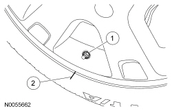
- Valve stem
- Reference mark
- NOTICE: For vehicles equipped with a Tire Pressure Monitoring
System (TPMS), the sensor may be damaged by incorrect tire mounting or
dismounting. Dismount the tire from the wheel as instructed in the
Disassembly and Assembly procedure. Failure to follow these instructions may
result in TPMS component damage.
NOTE: Always make sure that the final high spot and measurement values are permanently marked on the inward sidewall of the tire for reference during future wheel and tire service.
Using a suitable tire machine, separate the tire beads from the wheel.- Lubricate the tire beads using a suitable fast drying, corrosion inhibiting tire bead lubricant.
- Position the tire 180 degrees (half-way around) on the rim so the valve stem reference mark is now opposite the valve stem.
- Re-inflate the wheel and tire assembly to the specified air pressure and
measure the assembly again using a suitable dial indicator or Hunter Road
Force 9700 Series Wheel Balancer. Mark the second high spot on the tire.
- If the runout or Road Force is reduced to within specifications, the concern has been resolved. Balance the assembly and install on the vehicle using the Wheel-to-Hub Optimization procedure.
- If the second runout or Road Force measurement is still not within
specification and both high spots are close to each other (within 101.6 mm
[4 in] ), the root cause is probably the tire (the high spot followed the
tire).
- To be SURE that the tire is causing the high runout, it is necessary to have 2 runout or Road Force measurements that are not within specification and the high spots must be in approximately the same location on the tire's sidewall. If the tire is the cause, install a new tire, balance the assembly and install on the vehicle using the Wheel-to-Hub Optimization procedure.
- If the second high spot is not within 101.6 mm (4 in) of the first high spot, proceed to the next step.
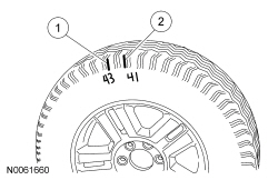
- First high spot on the tire
- Second high spot on the tire
- If the second high spot is still above specification and is within 101.6 mm (4 in) of being opposite the first high spot on the wheel, the root cause is probably the wheel (the high spot followed the wheel). Dismount the tire from the wheel, mount the wheel on a balancer and check the wheel runout. If the wheel runout exceeds 1.14 mm (0.045 in), install a new wheel, balance the assembly and install on the vehicle using the Wheel-to-Hub Optimization procedure.
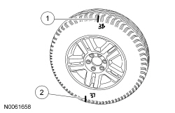
- First high spot on the tire
- Second high spot on the tire
- NOTE: If the second high spot did not follow the wheel or the
tire and the runout is still not within specification, improvements may be
made by rotating the tire 90 degrees (one-fourth turn).
Draw an arrow on the tire sidewall from the second high spot towards the first high spot (in the shortest direction).
- Separate the tire beads from the wheel and rotate the tire 90 degrees (one-fourth turn) in the direction of the arrow.
- First high spot on the tire
- Second high spot on the tire
Wheel-to-Hub Optimization
Wheel-to-hub optimization is important. Clearance between the wheel and hub can be used to offset or neutralize the Road Force or run-out of the wheel and tire assembly. For every 0.001 inch of wheel-to-hub clearance, the Road Force can be affected between 1 and 3 pounds depending on the tire stiffness.
NOTE: The example below illustrates how the clearance between the wheel and the hub can be used to offset the high spot of radial run-out or Road Force. Following the procedure will make sure of the best optimization.
- Position the wheel and tire assembly on the vehicle so that the high spot location of radial run-out or Road Force is at the 6 o'clock position and install the wheel nuts by hand until snug.
- NOTE: Do not allow the full weight of the vehicle to rest on the
tires while tightening the wheel nuts.
Lower the vehicle until the tires make contact with the ground, slightly loading the suspension. Tighten the wheel nuts as described in Wheel and Tire in this section.
Tire Pressure Monitoring System (TPMS)
Special Tool(s)
Principles of Operation
WARNING: The tire pressure monitoring system (TPMS) sensor battery may release hazardous chemicals if exposed to extreme mechanical damage. If these chemicals contact the skin or eyes, flush immediately with water for a minimum of 15 minutes and get prompt medical attention. If any part of the battery is swallowed, contact a physician immediately. When disposing of TPMS sensors, follow the correct procedures for hazardous material disposal. Failure to follow these instructions may result in serious personal injury.
The Tire Pressure Monitor (TPM) module monitors the tire pressure of all 4 road tires. The wheel-mounted tire pressure sensors transmit signals via radio frequency to the TPM module. The TPM module is a radio receiver that collects the tire pressure data from the tire pressure sensors. The TPMS sensor radio transmissions are sent once approximately every 60 seconds when the vehicle speed exceeds 32 km/h (20 mph). The data is then sent to the Body Control Module (BCM) where a predetermined pass/fail criteria is applied. The BCM compares each TPMS sensor transmission against a low-pressure limit. If it has been determined that the tire pressure has fallen below this limit, the BCM communicates this on the vehicle communication bus to the Instrument Panel Cluster (IPC). The IPC then illuminates the TPMS warning indicator and displays the appropriate message(s) in the message center.
Ambient Temperature Change and Tire Pressure
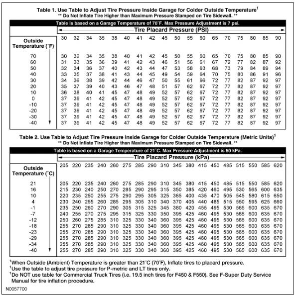
Tire pressures fluctuate with temperature changes. For this reason, tire pressure must be set to specification when tires are at outdoor ambient temperatures. If the vehicle is allowed to warm up to shop temperatures, and the outside temperature is less than shop temperature, the tire inflation pressure must be adjusted accordingly.
If the tires are inflated to specification at shop temperatures, and the vehicle is moved outdoors when the outdoor ambient temperature is significantly lower, the tire pressure may drop enough to be detected by the TPMS and activate the TPMS warning indicator.
As the ambient temperature decreases by 6ÂşC (10ÂşF), tire pressure decreases 7 kPa (1 psi). Adjust the tire pressure by 7 kPa (1 psi) for each 6ÂşC (10ÂşF) ambient temperature drop as necessary to keep the tire at the specified Vehicle Certification (VC) label pressure. Refer to the following tables to adjust the tire pressure indoors for colder outside temperatures.
Tire Pressure Monitoring System (TPMS) Warning Indicator and Message Center Messages
The TPMS warning indicator and vehicle message center sometimes display faults that cannot be resolved by the customer. Treat these messages as TPMS faults that must be serviced.
Tire Pressure Monitoring System (TPMS) Warning Indicator Illuminates Continuously
NOTE: When directed to train or re-train any TPMS sensors, use only the sensor training procedure outlined in Tire Pressure Monitoring System (TPMS) Sensor Training - Intelligent Access (IA). Do not use the TPMS reset procedure outlined in the Owner's Literature as this procedure will not program new sensors to the module.
The TPMS warning indicator remains on continuously and the message center displays LOW TIRE PRESSURE when any of the tire pressures are low. When this condition exists, adjust the tire pressure to the recommended cold pressure indicated on the VC label.
TPMS Warning Indicator Flashes
The TPMS warning indicator flashes for 70 seconds, then remains on continuously when the ignition switch is turned to the ON position when the TPMS is malfunctioning. The TP_STAT PID can be used to determine why the TPMS warning indicator is flashing.
- Tire Pressure Sensor Fault - The message center displays TIRE PRESSURE SENSOR FAULT when a TPMS sensor is malfunctioning. GO to Symptom Chart.
- No communication with the BCM. The TPMS warning indicator illuminates when the IPC has not received any signals from the BCM for more than 5 seconds. The message center displays TIRE PRESSURE MONITOR FAULT. GO to Symptom Chart.
- Tire Pressure Monitor Fault - The message center displays TIRE PRESSURE MONITOR FAULT when the TPMS is malfunctioning. GO to Symptom Chart.
Tire Pressure Monitoring System (TPMS) PID Definitions and Intermittent Troubleshooting
TPMS Status PID
The TPM monitors the TPMS status. The current status can be viewed by accessing the TPMS status PID: TPMS_STAT using the scan tool. This helps identify the current system status and may aid in diagnosing the system. The PID has 4 valid states:
- TPMS_STAT = SENSOR FAULT.
- If the module has not received the tire pressure status from 1 to 3 TPMS sensors for 20 minutes when the vehicle speed is above 32 km/h (20 mph), the PID displays SENSOR FAULT.
- TPMS_STAT = SYSTEM FAULT.
- If the module has not received the tire pressure status from all 4 TPMS sensors for 20 minutes and the vehicle speed is above 32 km/h (20 mph), the PID displays SYSTEM FAULT.
- TPMS_STAT = LOW.
- If the module has detected that at least 1 TPMS sensor is reporting low tire pressure, the PID displays LOW.
- TPMS_STAT = SYSTEM ACTIVE.
- If the TPMS is functioning normally, the PID displays SYSTEM ACTIVE.
TPMS Last Warning Event PID Definitions
The TPMS uses the TPMS last warning event PIDs to store detailed information about the last 5 times the TPMS warning indicator was activated. These PIDs can be used to acquire more information about a particular TPMS event.
EVT1_AGE_IGN through EVT5_AGE_IGN
The number of key cycles since the TPMS warning indicator was activated. This PID cycles from zero to 255. Default is $00, this can be used to determine how long ago a TPMS event occurred and the time (in key cycles) between events.
EVT1_TR_LOC through EVT5_TR_LOC
This is the last programmed location for the sensor identifier causing each TPMS event. Due to tire rotation, the sensor may no longer be at the original location. It is suggested that all the PIDs be recorded, the system retrained, and then the sensor identifier PIDs be used to pinpoint the actual location of each sensor.
EVT1_PRESS through EVT5_PRESS
This is the tire pressure associated with each TPMS warning indicator event. This can be used along with the function code to clearly identify the TPMS events that were strictly due to low pressure. It can also be used to determine when a sensor is transmitting inaccurate tire pressure.
EVT1_SNSR_ST through EVT5_SNSR_ST
Describes the warning status of each TPMS event by using the information received from the TPMS status (TPMS_STAT) PID. If there is a communication issue, the status could be Normal.
- Unknown
- Normal (normal operation)
- Low (low pressure event)
- Fault (sensor fault or system fault)
EVT1_SNSR_ID through EVT5_SNSR_ID
This is the identifier of the sensor involved in each TPMS event. EVT1 is the most recent event that triggered the TPMS warning indicator. Default is $ 00 00 00 00.
Wheel Rotation and Sensor Training Techniques
Moving a Problem Sensor/Wheel to a Different Position
If a sensor in a certain location has caused several events, yet the sensor trains and seems to operate normally, moving that particular wheel to a different location on the vehicle is a good way to isolate the issue to a certain sensor/wheel location. Rotate the wheels and road test the vehicle. This can be done in an attempt to replicate the issue. This determines if the issue followed the sensor or remained in the original sensor location.
Training Sensors in a Different Order
This is a technique to get past a left front sensor that may not be responding to determine if the remaining sensors train to the module. This can help save time determining if other sensors are having issues or if the module is experiencing training difficulties with a certain location.
Training Known Good Sensors From Another Vehicle
Training known good sensors from another vehicle cannot differentiate between a faulted module and Radio Frequency Interference (RFI), as some noise source could be preventing the TPM module from receiving the tire pressure status from the original sensors as well as the known good sensors. This technique can be used to differentiate between a sensor and module issue. If the TPM module cannot train any of the sensors on the same vehicle, and likewise cannot train known good sensors from another vehicle, then the issue is with the TPM module or RFI and not with the original sensors. The original sensors should not be replaced.
Items That Cause RFI
Non-OEM Equipment
The following equipment has been found to sometimes cause RFI :
- Video equipment has been found to cause RFI especially when the video and power supply lines are near the TPMS.
- Car alarms (even those installed by dealerships) have been found to create enough RFI to cause the TPMS to malfunction or lose considerable range. These car alarms can sometimes be difficult to locate, as they are usually hidden somewhere out of the way for reduced accessibility.
- Many different in-vehicle cell phone chargers have been found to cause considerable RFI. The vehicles with the power point closest to the TPM are the most affected. It must be noted that most cell phone chargers do not produce high levels of RFI all the time. This depends on the state of charge of the cell phone battery. The phone must be almost completely discharged in some cases.
- Power supplies and DC/AC inverters typically create a lot of RFI. Most consumer grade equipment has very little filtering or shielding.
OEM Modules
In some cases, the RFI may actually be caused by a module or ground on the vehicle. Depending on the severity of the issue, a dirty ground, improperly built ground shield or module can disable the system. Modules that have microcontrollers using clock circuits to create the timing pulses for the microprocessor may radiate RFI.
Using Customer's Electronics to Pinpoint the Radio Frequency Interference (RFI) Source
This can be a way to determine the cause of an issue well before the sensors and module are replaced with little or no affect on the system performance. Since this takes more up-front work, it relies on working with the customer to determine what equipment was being used at the time of the event.
Options for Eliminating Intermittent TPMS Conditions Caused by RFI
- If an OEM component or customer device is causing an RFI issue, replace the device.
- If a phone charger is causing an RFI issue, the customer should consult their cell phone provider to acquire a different phone charger.
- If a device such as a dealer-installed alarm is causing an RFI issue, move the device to another location on the vehicle. In the case of a portable device, move the power cord to another power point location.
In summary, if the RFI source is present and cannot be moved or replaced, the intermittent issue remains. The vehicle owner must accept RFI and the unwanted system operation it can cause.
Inspection and Verification
- Keep the following items in mind when diagnosing any TPMS related issue:
- The tire pressure sensors are not designed to be used with aftermarket wheels. The use of run-flat tires (tires with steel body cord plies in the tire sidewall) that are not originally equipped, may block the TPMS signal and are not recommended.
- Non-OEM modifications made to the vehicle may result in false TPMS warnings.
- Swapping wheels on vehicles with the same TPMS sensors sets a fault if the sensors are not trained. Refer to Tire Pressure Monitoring System (TPMS) Sensor Training - Intelligent Access (IA) or Tire Pressure Monitoring System (TPMS) Sensor Training - Integrated Keyhead Transmitter (IKT) in this section.
- The tire pressure calibrations in the TPM for the system cannot be changed to use lower tire pressures than those listed on the Vehicle Certification (VC) label.
- Certain non-OEM electronic equipment may cause RFI and false TPMS warnings. To aid in diagnosis, obtain information from the owner regarding any equipment that has been added or was in use at the time the TPMS fault occurred.
- It may be necessary to disconnect any electronic add-on equipment to verify its impact on TPMS operation. For intermittent cases, it may be necessary to ask the customer to provide portable electronic equipment to verify its impact on the system.
- Visually inspect for obvious signs of mechanical or electrical damage.
- If an obvious cause for an observed or reported concern is found, correct the cause (if possible) before proceeding to the next step.
- NOTE: Make sure to use the latest scan tool software release.
If the cause is not visually evident, connect the scan tool to the Data Link Connector (DLC).
- NOTE: The Vehicle Communication Module (VCM) LED prove-out
confirms power and ground from the DLC are provided to the VCM.
If the scan tool does not communicate with the VCM :
- check the VCM connection to the vehicle.
- check the scan tool connection to the VCM.
- refer to Section 418-00, No Power To The Scan Tool, to diagnose no power to the scan tool.
- If the scan tool does not communicate with the vehicle:
- verify the ignition is ON.
- verify the scan tool operation with a known good vehicle.
- refer to Section 418-00 to diagnose no response from the PCM.
- Carry out the network test.
- If the scan tool responds with no communication for one or more modules, refer to Section 418-00.
- If the network test passes, retrieve and record Continuous Memory Diagnostic Trouble Codes (CMDTCs).
- Clear the CMDTCs and carry out the self-test diagnostics for the TPM module and BCM.
- If the DTCs retrieved are related to the concern, go to the BCM DTC Chart or the TPM Module DTC Chart. For all other DTCs, refer to the Master DTC Chart in Section 419-10.
- If no DTCs related to the concern are retrieved, GO to Symptom Chart.
DTC Charts
Body Control Module (BCM) DTC Chart
Tire Pressure Monitor (TPM) Module DTC Chart
Symptom Chart
NOTE: Training the sensors is not necessary after a tire rotation.
Failure of a TPMS component may not cause the message center to display a fault message or store a DTC. The Symptom Chart is a starting point to begin diagnosis of these concerns.
Pinpoint Tests
Pinpoint Test D: Tire Pressure Monitoring System (TPMS) Warning Indicator On Continuously and Message Center Displays LOW TIRE PRESSURE
Normal Operation
The Tire Pressure Monitor (TPM) module monitors the tire pressure of all 4 road tires. The wheel-mounted tire pressure sensors transmit data via radio frequency signals to the TPM module. The TPM module is a radio receiver that collects the tire pressure data from the Tire Pressure Monitoring System (TPMS) tire pressure sensors. The data is then sent to the Body Control Module (BCM) where a predetermined pass/fail criteria is applied. The TPMS sensor radio transmissions are sent approximately once every 60 seconds when the vehicle speed exceeds 32 km/h (20 mph). The BCM compares each TPMS sensor transmission against a low-pressure limit. If it has been determined that the tire pressure has fallen below this limit, the BCM communicates this on the vehicle communication bus to the Instrument Panel Cluster (IPC). The IPC then illuminates the TPMS warning indicator and displays the appropriate message(s) in the message center.
This symptom can also be caused by a spare tire currently being used in place of a road tire. Make sure the spare tire is not currently in use.
-
This pinpoint test is intended to diagnose the following:
- Tire pressure not set to specifications listed on the Vehicle Certification (VC) label
- Spare tire currently in use
- TPMS sensor(s)
PINPOINT TEST D: TPMS WARNING INDICATOR ILLUMINATES CONTINUOUSLY AND MESSAGE CENTER DISPLAYS LOW TIRE PRESSURE
NOTE: Use only the Digital Tire Pressure Gauge any time tire pressures are measured to be sure that accurate values are obtained.
NOTE: If a warranty case is opened for an actual TPMS fault, document and include the actual tire pressure data in all warranty communications.
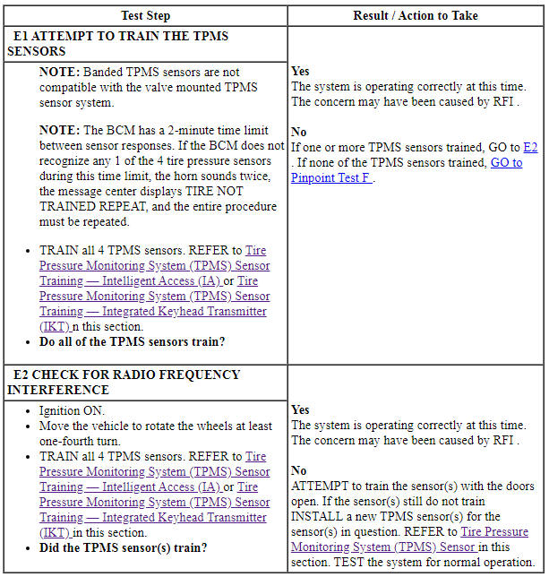
Pinpoint Test E: One Or More TPMS Sensors Do Not Train And No DTCs Are Present
NOTE: If the vehicle has been stationary for more than 30 minutes, the sensors go into a "sleep mode" to conserve battery power. It becomes necessary to wake them up so they transmit the latest tire pressure information to the TPM module. For additional information, refer to Tire Pressure Monitoring System (TPMS) Sensor Activation in this section.
Normal Operation
The Body Control Module (BCM) monitors the tire pressure of all 4 road tires. The wheel-mounted tire pressure sensors transmit signals via radio frequency to the Tire Pressure Monitor (TPM) module. The TPM module is a radio receiver that collects the tire pressure data from the tire pressure sensors and sends that information to the BCM. The TPMS sensor radio transmissions are sent once approximately every 60 seconds when the vehicle speed exceeds 32 km/h (20 mph). The BCM learns the position on the vehicle of each TPMS sensor through the training process. Refer to Tire Pressure Monitoring System (TPMS) Sensor Training - Intelligent Access (IA) or Tire Pressure Monitoring System (TPMS) Sensor Training - Integrated Keyhead Transmitter (IKT) in this section for the complete sensor training procedure.
-
This pinpoint test is intended to diagnose the following:
- TPMS sensors
- Radio Frequency Interference (RFI)
PINPOINT TEST E: ONE OR MORE TPMS SENSORS DO NOT TRAIN AND NO DTCs ARE PRESENT
Pinpoint Test F: Body Control Module (BCM) Cannot Enter Sensor Training Mode When Using the Tire Pressure Monitoring System (TPMS) Sensor Training Procedure
Normal Operation
For the Body Control Module (BCM) to enter Tire Pressure Monitoring System (TPMS) sensor training mode, the BCM must receive valid inputs from the stoplamp switch (off) and ignition switch (run), and it must receive valid vehicle speed sensor input (0 km/h [0 mph] ). Refer to Tire Pressure Monitoring System (TPMS) Sensor Training - Intelligent Access (IA) or Tire Pressure Monitoring System (TPMS) Sensor Training - Integrated Keyhead Transmitter (IKT) in this section for the complete sensor training procedure.
-
This pinpoint test is intended to diagnose the following:
- Stoplamp switch concern
- Ignition switch concern
- BCM
PINPOINT TEST F: BCM CANNOT ENTER SENSOR TRAINING MODE WHEN USING THE TPM SENSOR TRAINING PROCEDURE
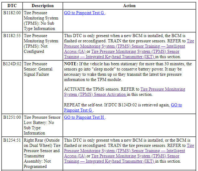
Pinpoint Test G: Tire Pressure Monitoring System (TPMS) Warning Indicator Is On With DTCs Present
Normal Operation
If there is a fault with 1, 2 or 3 of the Tire Pressure Monitoring System (TPMS) sensors, DTC B124D:02 sets. The TPMS warning indicator flashes for 70 seconds and then remains on continuously when the ignition switch is turned to the ON position and the message center displays TIRE PRESSURE SENSOR FAULT.
If the Tire Pressure Monitor (TPM) module does not get a response from all 4 of the TPMS sensors and transfers that information to the BCM, DTC B1182:00 also sets and the message center displays TIRE PRESSURE MONITOR FAULT.
It should be noted that TPMS sensor communication to the TPM module can be interrupted by radio frequency noise, which can cause intermittent issues that are not vehicle concerns. Radio frequency noise is generated by electrical motors and appliance operation, cellular telephones, remote transmitters, power inverters and portable entertainment equipment. Anytime the TPMS sensor training procedure is performed successfully, the warning indicator is extinguished and the vehicle must be driven for 18-20 minutes before the TPM module sets a fault.
- DTC B1182:00 (Tire Pressure Monitoring System (TPMS): No Sub Type Information) - set by the BCM when all 4 of the tire pressure sensors are faulted, missing, not responding or when not heard by the TPM module.
- DTC B124D:02 (Tire Pressure Sensor: General Signal Failure) - set by the BCM when 1, 2 or 3 of the tire pressure sensors are faulted or not responding, or not heard by the TPM module.
- TPMS_STAT = SENSOR FAULT - when the BCM does not receive the tire pressure status for 1 to 3 TPMS sensors for 20 minutes when the vehicle speed is above 32 km/h (20 mph), the PID displays SENSOR FAULT.
- TP_STAT = SYSTEM FAULT when the BCM does not receive the tire pressure status for all 4 TPMS sensors for 20 minutes when the vehicle speed is above 32 km/h (20 mph).
-
This pinpoint test is intended to diagnose the following:
- Not all TPMS sensors are installed
- TPMS sensors not trained
- TPMS sensor(s)
- Intermittent TPMS operation due to RFI
- TPM module wiring
- TPM module
- BCM wiring
- BCM
PINPOINT TEST G: TPMS WARNING INDICATOR IS ON WITH DTCs PRESENT
Pinpoint Test H: DTC B1251:00
-
Normal Operation
- DTC B1251:00 (Tire Pressure Sensor Low Battery: No Sub Type Information) - sets when there is a fault in the Tire Pressure Monitoring System (TPMS), such as a damaged or missing TPMS sensor(s), or when attempting to train a TPMS sensor(s) with a low battery. The TPMS warning indicator flashes for 70 seconds and then remains on continuously when the ignition switch is turned to the ON position, and the message center displays TIRE PRESSURE SENSOR FAULT.
Training the sensors detects any TPMS sensors with batteries low enough so that the sensor will not transmit tire pressure data, these sensors will not train.
-
This pinpoint test is intended to diagnose the following:
- TPMS sensor(s)
PINPOINT TEST H: DTC B1251:00
Pinpoint Test I: DTC U0140:87
-
Normal Operation
- DTC U0140:87 (Lost Communication With Body Control Module: Missing Message) - set by the Tire Pressure Monitor (TPM) module if data messages received from the BCM are missing. For a complete list of all network messages, refer to Section 418-00.
This pinpoint test is intended to diagnose the following:
- Communication network concern
- TPM module
- BCM
PINPOINT TEST I: DTC U0140:87
 Specifications, Description and Operation
SPECIFICATIONS
Material
General Specifications
Torque Specifications
a Refer to the procedure in this section.
DESCRIPTION AND OPERATION
Wheels And Tires
Safety Precautions
WARNING:
Vehicle m ...
 General Procedures, Removal and Installation
GENERAL PROCEDURES
Tire Pressure Monitoring System (TPMS) Sensor Training - Integrated Keyhead
Transmitter (IKT)
Special Tool(s)
NOTE: If the vehicle has been stationary for more than 30 minute ...
Other materials:
Crash sensors and airbag indicator
WARNING: Modifying or adding equipment to the front end of
your vehicle (including frame, bumper, front end body structure
and tow hooks) may affect the performance of the airbag system,
increasing the risk of injury. Do not modify the front end of your
vehicle.
Your vehicle has a collection of ...
Assembly
Engine
Special Tool(s)
Material
Engine Upper
Engine Front
Engine Upper - LH Cylinder Head
Engine Upper - RH Cylinder Head
Timing Drive Components
Lower Engine Block (View 1)
Lower Engine Block (View 2)
NOTICE: During engine repair procedures, cleanliness is extremely
importa ...
Assembly
Engine
Special Tool(s)
Material
Engine Upper
Engine Front
Engine Upper - LH Cylinder Head
Engine Upper - RH Cylinder Head
Timing Drive Components
Lower Engine Block (View 1)
Lower Engine Block (View 2)
NOTICE: During engine repair procedures, cleanliness is extremely
i ...
