SPECIFICATIONS
General Specifications
Torque Specifications
DESCRIPTION AND OPERATION
Charging System
Overview
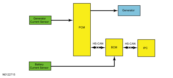
The generator is driven by the accessory drive belt. When the engine is started, the generator begins to generate AC voltage which is internally converted to DC voltage. The DC voltage is controlled by the voltage regulator (located on the rear of the generator) and supplied to the battery. The PCM controls the voltage regulation setpoint, working with the generator internal voltage regulator over 2 control and communication circuits.
This vehicle is equipped with load shed strategy. With the engine off, the BCM monitors the battery state of charge using the battery current sensor attached to the negative battery cable. With the engine running, the BCM monitors system voltage to the BCM and PSCM.
The PCM monitors the generator current using the generator current sensor attached to the generator B+ battery cable. The information supplied to the PCM from the generator current sensor is used by the PCM to adjust the engine idle stability and torque control.
System Operation
System Diagram
Network Message Chart
Module Network Input Messages - BCM
Module Network Input Messages - IPC
Module Network Input Messages - PCM

Charging System
The PCM-controlled, or Smart Charge charging system determines the optimal voltage setpoint for the charging system and communicates this information to the voltage regulator. The Smart Charge charging system is designed to set 1 of 6 DTCs any time a charging system fault is present. All of the DTCs can set continuous faults, but not all DTCs set as on-demand faults.
This system uses 2 communication lines between the PCM and the generator/voltage regulator. Both of these communication lines use PWM. The generator communication (GENCOM) line communicates the desired setpoint from the PCM to the voltage regulator. The generator monitor (GENMON) line communicates the generator load and error conditions to the PCM. The GENCOM command is only sent by the PCM when it is necessary to adjust the voltage setpoint. If the setpoint does not need to be changed, several seconds may elapse between PCM GENCOM commands. This normal operation appears in the PID as occasional bursts of pulse-width commands. The third pin on the voltage regulator, the "A" circuit pin, is a circuit dedicated to monitor or sense battery voltage.
The PCM simultaneously controls and monitors the output of the generator. When the current consumption is high or the battery is discharged, the PCM raises engine speed as needed to increase generator output. The generator charges the battery and at the same time supplies power for all required electrical loads. The battery is more effectively charged with a higher voltage when the battery is cold and a lower voltage when the battery is warm. The PCM uses a signal from the IAT sensor to adjust the charging voltage according to the battery temperature. The PCM also uses other inputs to control the charging system voltage such as the VSS and engine coolant temperature. The voltage setpoint is calculated by the PCM and communicated to the voltage regulator by the GENCOM circuit based on the needs of the vehicle and the conditions.
The PCM turns off the generator during cranking to reduce the generator load and improve cranking speed. Once the engine starts, the PCM slowly increases generator output to the desired voltage.
The PCM reports any charging system faults and sends a message through the HS-CAN to the BCM. The BCM controls the charging system warning indicator by sending a message over the MS-CAN to the IPC. The IPC then controls charging system warning indication based on the message from the PCM through the BCM. The status of the PCM charging system warning indicator and/or message is confirmed by viewing PCM PID generator fault indicator lamp (GENFIL). Any charging system fault detected by the PCM results in 1 or more DTCs being set and the PID GENFIL having a status of On. If equipped with a charging system warning indicator, the IPC turns the indicator on or off. If equipped with a message center, the IPC displays a CHECK CHARGING SYSTEM message. In some instances, the CHECK CHARGING SYSTEM message may not display if the ignition is ON and the engine is off.
Under certain circumstances, the charging system may have a concern, but still keeps the battery charged and the vehicle running. GENCOM normally initiates charging, but the generator may charge with a fault in this circuit. If the engine operates at more than 2,000 RPM momentarily, the generator may self-excite or start charging on its own. The charging system warning indicator is illuminated and/or CHECK CHARGING SYSTEM message is displayed, and the generator operates in a default mode (approximately 13.5 volts) until the engine is turned off. When the engine is restarted and the engine operates at more than 2,000 RPM momentarily, the generator may again self-excite and again the charging system warning indicator is illuminated and/or CHECK CHARGING SYSTEM message is displayed.
The PIDs and their associated descriptions used in the charging system diagnosis are listed below:
Battery Management System
NOTICE: When any vehicle module is being programmed, connect an external battery charger to make sure the module programming is completed without the interruption due to the load shedding feature becoming active. The external battery charger must maintain a system voltage above 13 volts. This may require a charger setting higher than the lowest charge setting. The external battery charger negative connection must be made to an engine or vehicle chassis ground and not the negative battery terminal. If the connection is to the negative battery terminal, load shedding cannot be prevented from being invoked and module programming may be corrupted. After charging has begun, start the engine to clear any load shed states and then turn the engine off and proceed with programming.
This vehicle is equipped with load shed strategy. The BCM monitors the battery state of charge using the battery current sensor attached to the negative battery cable and the system voltage supplied to the BCM during 8 continuous hours of vehicle sleep time (key off with doors closed).
To maintain correct operation of the load shed system, ground any electrical devices or equipment to the chassis ground and not the negative battery terminal. A connection to the negative battery terminal may cause an inaccurate measurement of the battery state of charge and may cause incorrect load shed system operation.
Engine Off Load Shed
The BCM uses the battery current sensor to keep track of the battery state of charge. The battery current sensor is a Hall-effect sensor attached to the battery ground cable. When the engine is off and the BCM determines the battery state of charge is below 40%, or 10% of the charge has been drained, or 45 minutes have elapsed, a load shed message is sent over the CAN. This message turns off the audio/navigation system to save the remaining battery charge. Under this condition the FCDIM (without touchscreen controls) displays SYS OFF TO SAVE BATT or the FDIM (with touchscreen controls) displays BATTERY SAVER - SYSTEM OFF PLEASE START THE ENGINE to notify the driver that battery protection actions are active.
Engine off load shedding occurs when the engine is not running and the ignition is in the ACC, RUN or delayed accessory position. This load shed state clears once the vehicle has been started and the battery state of charge recovers. If the engine off load shed occurs, the audio/navigation system turns off.
When the ignition is in the RUN position and if load shed occurs, the IPC message center may display either TURN POWER OFF TO SAVE BATT (base message center) or TURN POWER OFF TO SAVE BATTERY (optional message center). The audio/navigation system shuts down after the message center displays the warning.
If a fault occurs with the battery current sensor or circuit(s), the only engine off load shed strategy that is active is a 45 minute timer. After 45 minutes have elapsed, the audio/navigation system turns off. To clear the load shed state, restart the engine.
For charging the vehicle battery, REFER to Section 414-01.
If the vehicle battery is charged by connecting the battery charger to the battery negative terminal or the battery is replaced, carry out the BMS Reset using the scan tool. If the BMS Reset is not carried out, it takes approximately 8 hours for the BCM to learn the new battery state of charge. During this 8 hour period, the vehicle must be undisturbed, with no doors opened or keyless entry button presses. If the vehicle is used before the BCM is allowed to learn the new battery state of charge, engine off load shedding can still occur and a message may display.
If the vehicle battery is charged by connecting the battery charger to the engine or chassis ground, the BMS Reset using the scan tool is not necessary.
If the vehicle has been jump started, test the battery condition. REFER to Section 414-01.
Engine Running Load Shed
When the BCM and/or PSCM voltage is low, with the engine running, the BCM sends a message to either minimize or shut down the climate controlled seats, rear defrost, heated mirrors and DATC blower motor to improve system voltage. Under this condition, the IPC message center displays either LOW BATTERY LESS FEATURES (base message center) or LOW BATTERY FEATURES TEMPORARILY TURNED OFF (optional message center) to notify the driver that battery protection actions are active.
There are 3 states of engine running load shed:
- Load shed 1
- Load shed 2 transient
- Load shed 2 continuous
Component Description
Generator
The generator is equipped with an internal voltage regulator and if equipped, the radial arm is serviceable separately.
Battery Current Sensor
The battery current sensor is attached to the negative battery cable. It is supplied a 5-volt reference voltage and a ground from the BCM. The battery current sensor is a Hall-effect sensor that supplies a PWM feedback signal to the BCM.
Generator Current Sensor
The generator current sensor is attached to the generator B+ cable. It is supplied a 5-volt reference voltage and a ground from the PCM. The generator current sensor is a Hall-effect sensor that supplies a analog feedback signal to the PCM.
Powertrain Control Module (PCM)
The PCM receives input signals from sensors and other components (switches, relays). Based on this information, the PCM generates output signals to control various relays, solenoids and actuators.
 Charging System
...
 Diagnosis and Testing
Charging System
Special Tool(s)
DTC Charts
Diagnostics in this manual assume a certain skill level and knowledge of
Ford-specific diagnostic practices. REFER to Diagnostic Methods in Section ...
Other materials:
Refueling
WARNING: Fuel vapor burns violently and a fuel fire can cause
severe injuries. To help avoid injuries to you and others:
• Read and follow all the instructions on the pump island.
• Turn off your engine when you are refueling.
• Do not smoke if you are near fuel or refueling your vehic ...
Frame and Mounting
Uni-Body, Subframe and Mounting System
SPECIFICATIONS
Torque Specifications
DESCRIPTION AND OPERATION
Subframe and Mounting Systems
The front subframe is bolted to the body and:
aids in structural support.
provides the mounting surface for the steering gear, the front
suspension lower arms, en ...
Specifications, Description and Operation
SPECIFICATIONS
Material
Torque Specifications
DESCRIPTION AND OPERATION
Handles, Locks, Latches and Entry Systems
Overview
The power lock/unlock feature locks or unlocks the doors upon a customer
request from either door lock control switch in the vehicle, a RKE transmitter,
or t ...
