SPECIFICATIONS
Material
a 6F50 transmission.
b 6F55 transmission.
Torque Specifications
a Refer to the procedure in this section.
General Specifications
Solenoid Operation Chart
b Turns off above 8 km/h (5 mph).
NC = Normally closed
NH = Normally high
NL = Normally low
Pressure Chart
Clutch Application Chart
H = Holding
D = Driven
Stall Speed Chart
Gear Ratio Chart
Shift Speeds
Differential and Transfer Gear Bearing Preload Shim Selection Chart
DESCRIPTION AND OPERATION
Automatic Transmission
Component Location
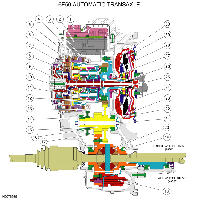
- Solenoid body
- Valve body
- Forward clutch (clutch brake 1,2,3,4)
- Low OWC
- Low/reverse clutch (clutch brake L/R)
- Intermediate clutch (clutch brake 2,6)
- Direct clutch (drive clutch 3,5,R)
- Overdrive clutch (drive clutch 4,5,6)
- Front planetary assembly
- Center planetary assembly
- Rear planetary assembly
- Differential transfer drive gear
- Differential transfer driven gear
- Transfer shaft roller bearing and cup
- Differential drive pinion gear
- Park gear
- Differential ring gear
- Fluid filter
- Differential roller bearing and cup
- Differential carrier gear and case assembly
- Differential lube tube
- Torque converter
- TCC
- Torque converter cover
- Support assembly (converter reactor)
- Turbine/input shaft
- Chain and sprocket pump driver
- Reactor
- Turbine
- Impeller
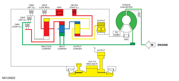
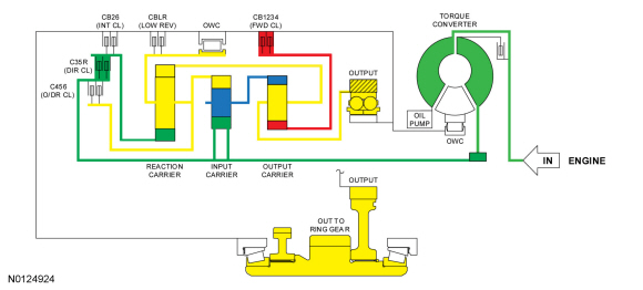
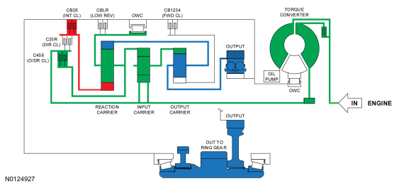
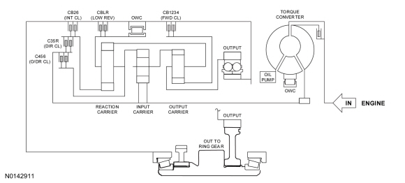
Overview
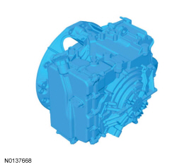
This automatic transmission is a 6-speed transmission with electronic shift control. It is designed for operation in a transverse powertrain for FWD and AWD vehicles.
This transmission has the following features:
- Six forward speeds
- Torque converter with an integral converter clutch
- Electronic shift and pressure controls
- Three planetary gearsets
- Three fixed multi-disc clutches
- Two multi-plate drive clutches
All hydraulic functions are directed by electronic solenoids to control the following:
- Engagement feel
- Shift feel
- Shift scheduling
- Modulated TCC applications
This transmission has a main control which contains:
- Solenoid body with TFT sensor
- Upper Valve body
- Lower Valve body
This automatic transmission is an electronically controlled transmission. Gear selection is achieved by the control of transmission fluid flow to operate various internal clutches. The PCM operates the electrical components and provides control of gear selection shift pressure, which increases refinement and torque converter slip.
In the event of a system fault, the PCM also provides for Failure Mode Effect Management to maintain maximum functional operation of the transmission with a minimum power reduction. In the event of a total loss of control or electrical power, the basic transmission functions P, R, N and D are retained. Also 5th gear is retained by the hydraulic system.
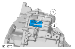
Identification Tags
Identification Tag Location
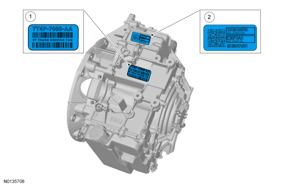
- Transmission identification tag
- Solenoid body identification tag
Transmission Identification Tag
- Transmission part number
- Transmission build date
- Transmission serial number
Original Solenoid Body Tag
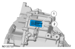
- 13 - digit solenoid body strategy
- 7 - digit solenoid body identification
Replacement Solenoid Body Tag
- 13 - digit solenoid body strategy
- 7 - digit solenoid body identification
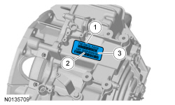
Solenoid Body Identification Tag
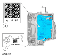
- 13 - digit solenoid body strategy
- 7 - digit solenoid body identification
System Operation
Park
Park Clutch Application Chart
H = Holding
Park Position Solenoid Operation Chart
NC = Normally Closed
NH = Normally High
NL = Normally Low
-
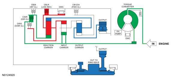
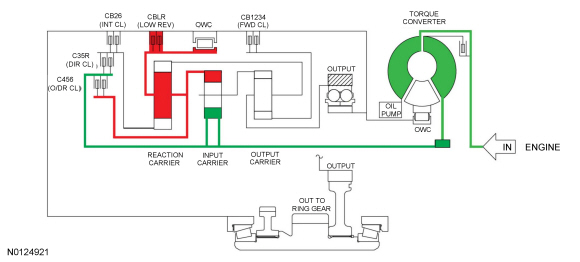
Powerflow
- With the selector lever in PARK, the low/reverse clutch holds the rear planetary carrier/center ring gear stationary.
- The park pawl holds the rear ring/front planetary carrier stationary.
- The turbine shaft drives the center sun gear.
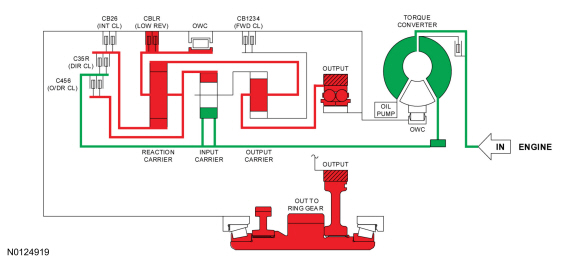
Reverse
Reverse Clutch Application Chart
H = Holding
D = Driving
Reverse Position Solenoid Operation Chart
NC = Normally Closed
NH = Normally High
NL = Normally Low
-
Powerflow
- With the selector lever in REVERSE, the low/reverse clutch holds the rear planetary carrier/center ring gear stationary.
- The direct clutch drives the rear sun gear.
- The rear ring/front planetary carrier transfers torque to the output hub in a reverse direction with a ratio of 2.88.
Neutral
Neutral Clutch Application Chart
H = Holding
Neutral Position Solenoid Operation Chart
NC = Normally Closed
NH = Normally High
NL = Normally Low
-
Powerflow
- With the selector lever in NEUTRAL, the low/reverse clutch holds the rear planetary carrier/center ring gear stationary.
- The turbine shaft drives the center sun gear.
1st Gear
NOTE: The transmission operates differently in 1st gear above and below 8 kmh (5 mph). Transmission operation is the same below 8 kmh (5 mph) and in the LOW position.
1st Gear Above 8 kmh (5 mph) Clutch Application Chart
H = Holding
1st Gear LOW Position and Below 8 kmh (5 mph) Clutch Application Chart
H = Holding
1st Gear Above 8 kmh (5 mph) Solenoid Operation Chart
NC = Normally Closed
NH = Normally High
NL = Normally Low
1st Gear LOW Position and Below 8 kmh (5 mph) Solenoid Operation Chart
NC = Normally Closed
NH = Normally High
NL = Normally Low
-
Powerflow
- In first gear, the forward clutch holds the front sun gear stationary.
- The rear planetary carrier/center ring gear is held stationary by the low OWC and/or the low reverse (1, R) clutch.
- The turbine shaft transfers torque to the center sun gear. The center sun gear transfers the torque to the center planetary carrier/front ring gear. The front ring gear transfers torque to the front planetary carrier/rear ring gear and the output hub to produce a ratio of 4.48.
2nd Gear
2nd Gear Clutch Application Chart
H = Holding
2nd Gear Solenoid Operation Chart
NC = Normally Closed
NH = Normally High
NL = Normally Low
-
Powerflow
- In second gear the forward clutch holds the front sun gear stationary.
- The intermediate clutch holds the rear sun gear stationary.
- The turbine shaft transfers torque to the center sun gear. The center sun gear transfers torque to the center ring gear/rear planetary carrier.
- The rear planetary carrier transfers the torque to the rear ring gear/front planetary carrier and the output hub to produce a gear ratio of 2.87.
3rd Gear
3rd Gear Clutch Application Chart
H = Holding
D = Driving
3rd Gear Solenoid Operation Chart
NC = Normally Closed
NH = Normally High
NL = Normally Low
-
Powerflow
- In third gear the forward clutch holds the front sun gear stationary.
- The direct clutch drives the rear sun gear.
- Power flows from the center sun gear to the center planetary carrier/front ring gear. From there, torque is transferred to the rear ring gear/front planetary carrier.
- Power also flows from the rear sun gear to the rear ring gear/front planetary carrier.
- The two inputs to the front planetary carrier combine and transfer torque to the output hub to produce a gear ratio of 1.84.
4th Gear
4th Gear Clutch Application Chart
H = Holding
D = Driving
4th Gear Solenoid Operation Chart
NC = Normally Closed
NH = Normally High
NL = Normally Low
-
Powerflow
- In fourth gear the forward clutch holds the front sun gear stationary.
- The overdrive clutch drives the rear planetary carrier/center ring gear.
- Power flows from turbine shaft to the center sun gear and center ring gear.
- The two inputs to the center planetary carrier combine and transfer torque to the front ring gear.
- The front ring gear transfers the torque to the front planetary carrier and onto the output hub to produce a gear ratio of 1.41.
5th Gear
5th Gear Clutch Application Chart
D = Driving
5th Gear Solenoid Operation Chart
NC = Normally Closed
NH = Normally High
NL = Normally Low
-
Powerflow
- In fifth gear the overdrive clutch drives the rear planetary carrier/center ring gear.
- The direct clutch drives the rear sun gear.
- The turbine shaft transfers torque to the center sun gear, rear sun gear, and rear planetary carrier/center ring gear.
- The torque from the three inputs locks the three planetary gearsets which produces a gear ratio of 1 to 1
-
Fail-safe Mode
- Because both SSD and SSB apply the clutches they control when they are turned OFF, 5th gear is the fail-safe.
6th Gear
6th Gear Clutch Application Chart
H = Holding
D = Driving
6th Gear Solenoid Operation Chart
NC = Normally Closed
NH = Normally High
NL = Normally Low
-
Powerflow
- In sixth gear the overdrive clutch drives the rear planetary carrier/center ring gear.
- The intermediate clutch holds the rear sun gear.
- The torque from the rear planetary carrier is transferred to the rear ring gear/front planetary carrier and the output hub which produces a gear ratio of 0.74.
Electrical System
Component Location
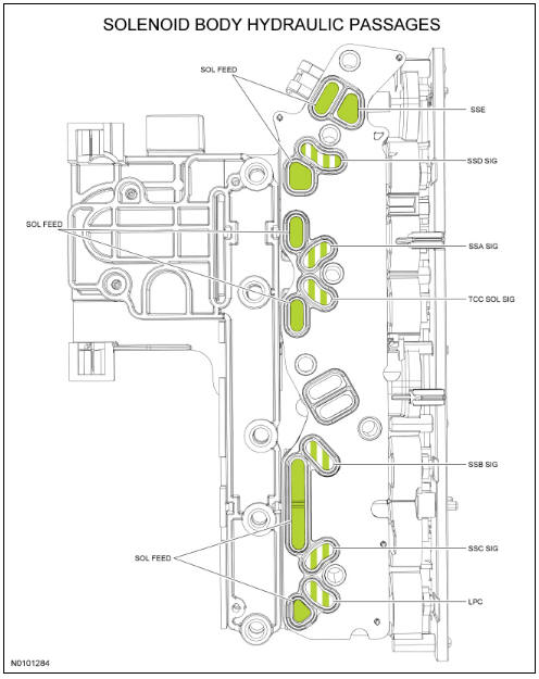
The solenoid body contains 5 shift solenoids, 1 TCC solenoid and 1 LPC solenoid.
Solenoid Body
- SSE
- SSD
- SSA
- TCC
- SSB
- SSC
- LPC
System Operation
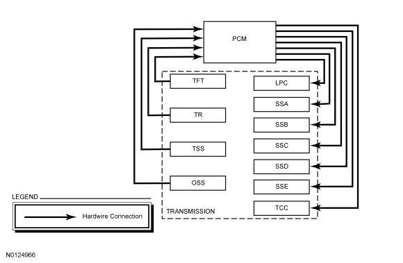
The PCM and its input/output network controls the following operations:
- Shift timing
- Line pressure (shift feel)
The transmission control strategy is separate from the engine control strategy in the PCM, although some of the input signals are shared. When determining the best operating strategy for transmission operation, the PCM uses input information from engine and driver related sensors and switches.
In addition, the PCM receives input signals from transmission related sensors and switches. The PCM uses these signals when determining transmission operating strategy.
Using all of these input signals, the PCM can determine when the time and conditions are right for a shift or when to apply or release the TCC. It also determines the best line pressure to optimize shift engagement feel. To accomplish this, the PCM uses output solenoids to control transmission operation.
Active Transmission Pursuit Mode (ATPM)
ATPM is a feature within the transmission software that enables the transmission to be more aggressive with shifting during aggressive driving (e.g. pursuit). Police vehicles have ATPM software that uses accelerator pedal, brake pedal, and steering position input to alter the shift scheduling for pursuit purposes.
The transmission software changes how the transmission shifts when it senses the vehicle is being driven aggressively and switches it back to save fuel when the aggressive driving is completed.
The software logic is made up of 2 parts:
- Brake torque-induced logic to handle downshifts under braking
- Upshift inhibit logic to hold gears around the corners; during corner exit, the transmission has not upshifted so there is no delay from the transmission downshifting out of a corner
-
Brake Torque Logic
- Uses brake line pressure and decleration rates as inputs and knows if the vehicle is performing an aggressive braking maneuver.
- If a set threshold is passed, the transmission software downshifts to the next possible gear during the braking event.
- The brake pressure threshold cannot be passed during normal driving maneuvers.
-
Upshift Inhibit Logic
- Uses lateral acceleration (cornering) to inhibit upshifts.
- When the lateral acceleration threshold is crossed (when the vehicle turns hard enough), the vehicle holds gears and upshifts only at redline.
- Stays active for 30 seconds after pursuit driving is completed, or deactivates when there is three continuous seconds of closed throttle.
Network Message Chart
Communication Message Chart
Component Description
Sensors and Switches
The PCM controls the electronic functions of this transmission. The PCM receives input signals from engine and transmission sensors and uses these inputs to control line pressure, shift time, TCC and shift solenoids.
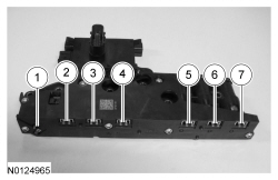
Solenoid Body
The solenoid body contains 7 solenoids: 5 shift solenoids ( SSA , SSB , SSC , SSD and SSE ), 1 TCC solenoid and 1 LPC solenoid. The TFT sensor is located in the solenoid body. The solenoid body is serviced as an assembly.
The solenoid body has a unique strategy data file that must be downloaded to the PCM. There is a 7-digit solenoid body identification and a 13-digit solenoid body strategy for each solenoid body. When a new solenoid body or transmission is installed, the scan tool must be used to get the solenoid body strategy data file and download it into the PCM.
If the PCM is replaced and the PCM data cannot be inhaled or exhaled, the solenoid body identification and solenoid body strategy must be downloaded into the PCM.
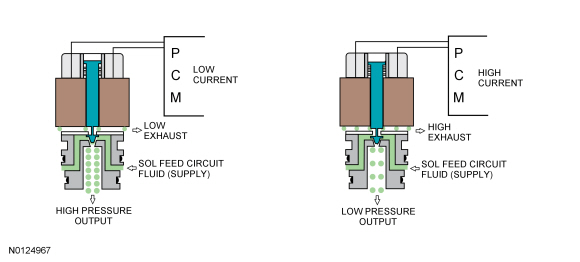
This transmission uses 3 types of solenoids: On/Off, normally low and normally high. On/Off solenoids open or close hydraulic passages based on the voltage signal it receives. Normally low solenoids provide hydraulic pressure proportional to supplied current. A normally low solenoid will not provide pressure without current, while it will supply high pressure with high current. Normally high solenoids provide pressure inversely proportional to supplied current. Normally high solenoids provide full output of pressure with no current and very low pressure with high current.
ON/OFF Solenoids
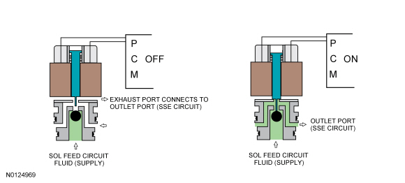
Normally Low Solenoids
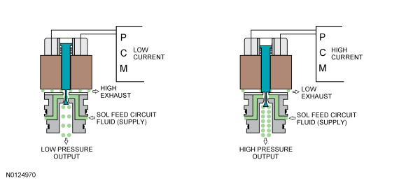
Normally High Solenoids
Hydraulic System
Component Location
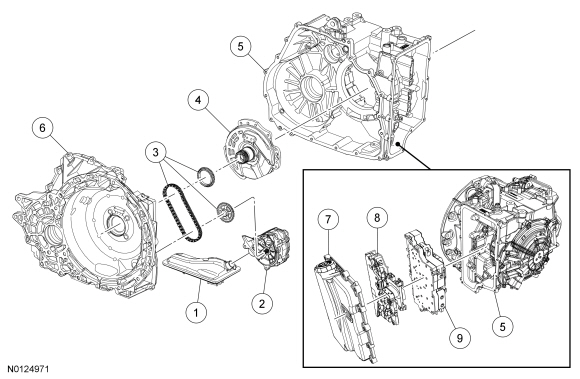
- Transmission fluid filter assembly
- Pump assembly
- Chain and sprocket assembly
- Stator support assembly
- Transmission case
- Torque converter housing
- Main control cover assembly
- Solenoid body
- Main control valve body
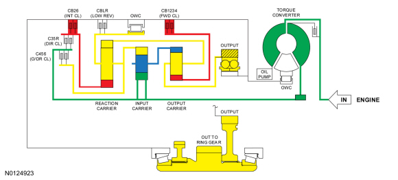
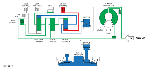
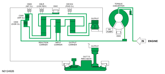
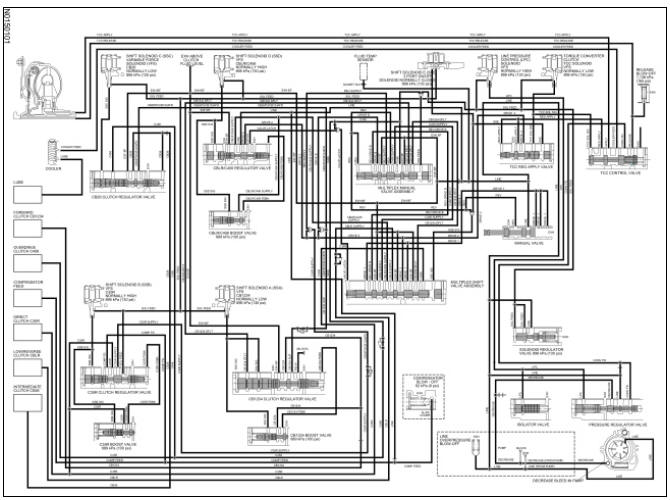
System Diagram
 Printable /
zoomable view of this graphic
Printable /
zoomable view of this graphic
Component Description
Transmission Pump and Fluid Filter
The transmission fluid in the sump area at the bottom of the transmission case flows through a transmission fluid filter to the pump assembly. The pump is bolted to the torque converter housing and is chain driven from a sprocket that is mounted on the stator support and turned by the torque converter.
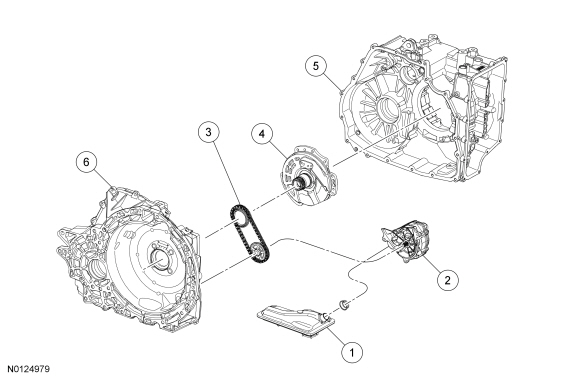
- Transmission fluid filter assembly
- Pump assembly
- Chain and sprocket assembly
- Stator support assembly
- Transmission case
- Torque converter housing
Transmission Fluid Level
The transmission fluid level is checked with the transmission at normal operating temperature between 82.3ÂşC (180ÂşF) and 93.4ÂşC (200ÂşF). The transmission fluid level indicator is part of the filler cap. The correct transmission fluid level is between the MIN and MAX in the cross hatches of the transmission fluid level indicator.
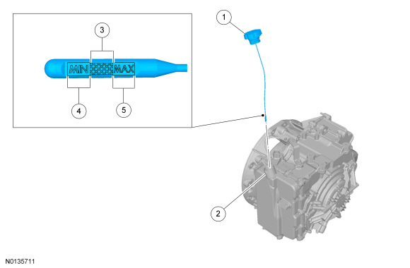
- Transmission fluid level indicator
- Main control cover assembly
- Correct transmission fluid level at normal operating temperature
- Low transmission fluid level at normal operating temperature
- High transmission fluid level at normal operating temperature
Main Control
The hydraulic system has a main control assembly. The main control assembly consists of a valve body and a solenoid body. The valve body contains the hydraulic regulator and multiplex shift valves. The solenoid body contains the shift solenoids that control the hydraulic valves. The solenoid body is serviced as an assembly and can not be disassembled. The solenoid body is controlled by the PCM. The PCM has software stored in it specific to the solenoid body currently in the transmission, called the solenoid body strategy. A new solenoid body strategy must be downloaded into the PCM any time a new solenoid body is installed.
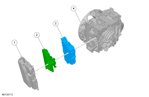
- Main control cover assembly
- Solenoid body
- Main control valve body
- Transmission case
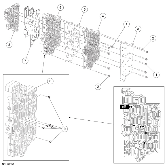
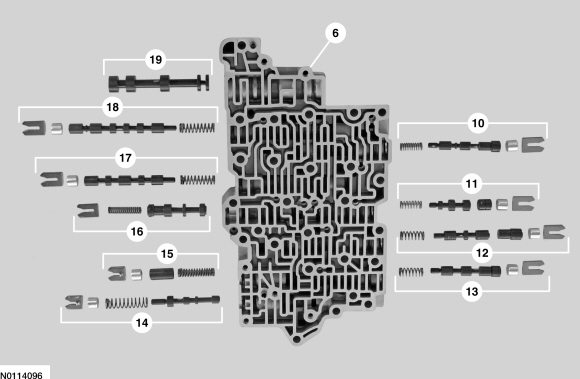
- Bolts -M6 x 63
- Bolts - M6 x 35
- Cover - transfer plate
- Case-to-valve body transfer plate
- Separator plate - valve body-to-transfer plate
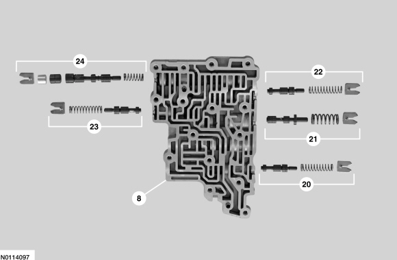
- Main control valve body
- Separator plate - main control valve body-to-lower valve body
- Lower valve body assembly
- Check balls
- Low/reverse and overdrive clutch regulator valve assembly
- Torque converter clutch regulator apply valve assembly
- Intermediate clutch regulator valve assembly
- Direct clutch regulator valve assembly
- Pressure regulator valve assembly
- Isolator valve assembly
- Torque converter clutch control valve assembly
- Multiplex manual valve
- Multiplex shift valve
- Manual valve
- Direct clutch boost valve assembly
- Solenoid regulator valve assembly
- Low/reverse and overdrive clutch boost valve assembly
- Forward clutch boost valve assembly
- Forward clutch regulator valve assembly
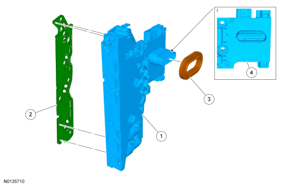
- Solenoid body
- Solenoid body filter
- Seal - solenoid body electrical connector
- Leadframe area
Multi-Plate Clutch
Multi-plate clutches are clutches that consist of multiple friction and steel clutch discs that when pressure is applied, either drive or hold (brake) components of the planetary gearset. This transmission has 5 multi-plate clutches:
- Forward (1, 2, 3, 4)
- Direct (3, 5, R)
- Intermediate (2, 6)
- Overdrive (4, 5, 6)
- Low/reverse
Both the direct (3, 5, R) and the overdrive (4, 5, 6) clutches are drive clutches. The direct (3, 5, R) clutch drives the rear planetary sun gear and the overdrive (4,5,6) clutch drives the rear planetary carrier. The forward (1, 2 ,3, 4), intermediate (2, 6) and the low/reverse clutches are brake clutches. The forward (1, 2, 3, 4) clutch holds the front sun gear, the intermediate (2, 6) clutch holds the rear sun gear and the low/reverse clutch holds the rear planetary carrier.
Clutches; overdrive (4, 5, 6) and direct (3, 5, R) are balanced in terms of dynamic pressure. That is, their pistons are exposed to the transmission fluid flow on both sides to prevent pressure buildup in the clutch as speed increases. This dynamic pressure equalization process is achieved by a baffle plate and pressure-free transmission fluid supply by a lubricating passage, through which the space between the piston and baffle plate is filled with transmission fluid.
The advantages of this dynamic pressure equalization are:
- reliable clutch engagement and release in all speed ranges.
- improved shift refinement.
External Sealing
The torque converter housing has a lip-type seal that seals the torque converter hub. The manual control lever shaft and half shafts also use lip-type seals. AWD vehicles do not use a RH half shaft seal, the transmission is sealed by the PTU on the RH side.
The torque converter housing is sealed to the transmission case with silicone sealant.
The transmission cover is sealed to the transmission case with a reusable gasket. The main control cover is sealed to the transmission case and the solenoid body with reusable rubber gaskets.
The TSS sensor is sealed to the transmission cover with an O-ring seal. The transmission fluid filler tube is sealed to the main control cover with an O-ring seal that is serviced with the transmission fluid filler tube. The transmission fluid level indicator is sealed to the transmission fluid filler tube with an O-ring seal that is serviced with the transmission fluid level indicator.
The line pressure tap plug, transmission fluid drain plug and the lubrication circuit tap plug have pipe threads and seal when tightened to specification.
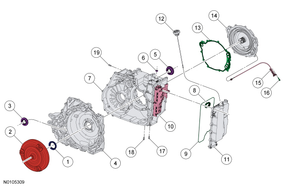
- Torque converter hub seal
- Torque converter
- RH halfshaft seal ( FWD only)
- Torque converter housing
- LH halfshaft seal
- Transmission case
- Main control cover-to-solenoid body seal
- Main control cover gasket
- Solenoid body assembly
- Main control cover
- Transmission fluid level indicator
- Transmission fluid level indicator
- Transmission case-to-transmission cover gasket
- Transmission cover
- TSS sensor
- TSS sensor bolt
- Line pressure tap plug
- Transmission fluid drain plug
- Lubrication circuit tap plug
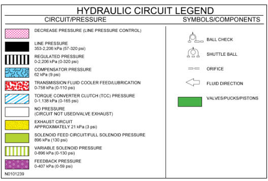
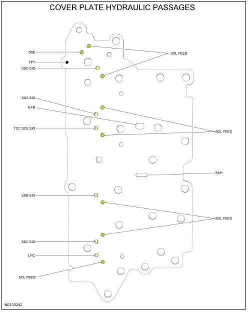
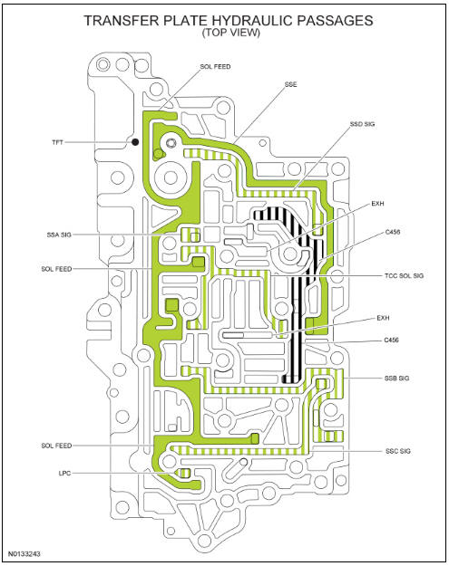
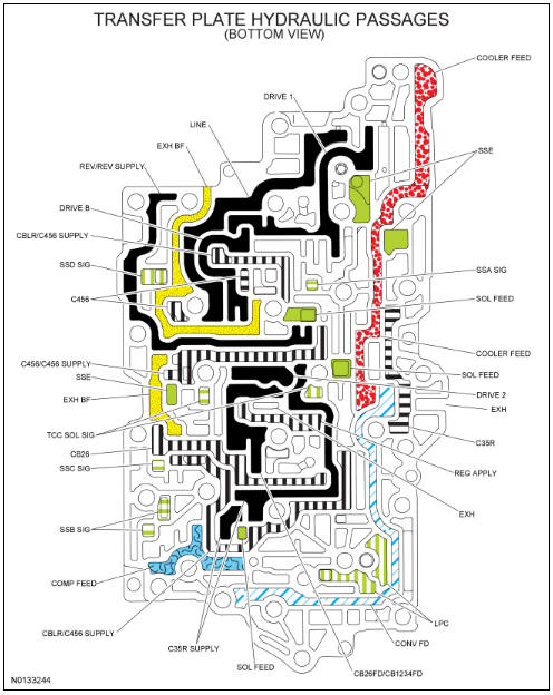
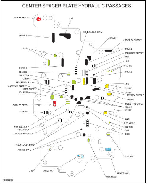
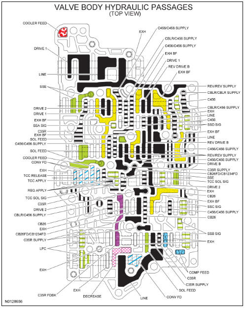
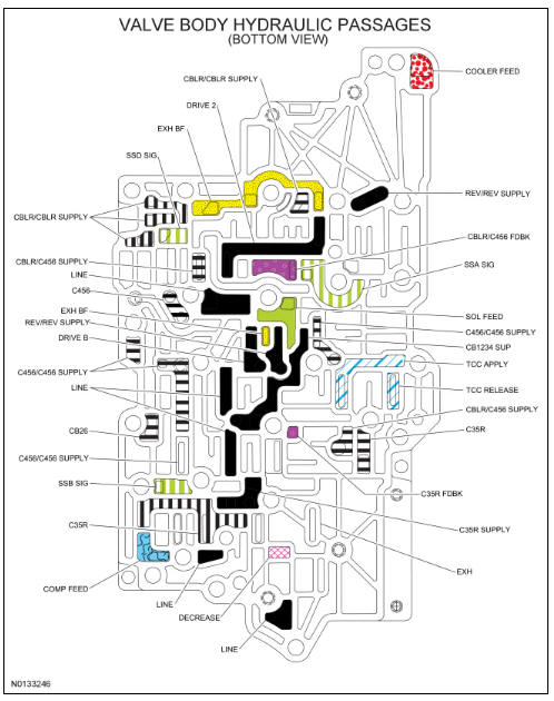
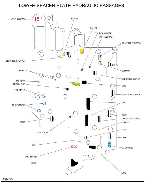
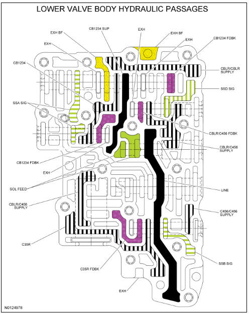
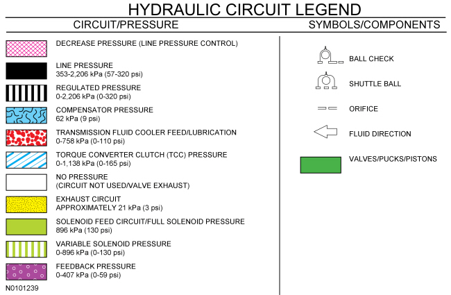
Hydraulic Circuits Legend
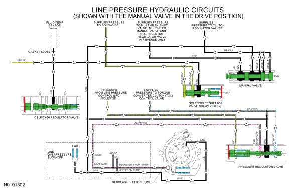
Line Pressure Hydraulic Circuits
The PCM controls line pressure with the LPC solenoid. This affects shift feel and apply component operation.
When the engine is running, the pump supplies pressure to the pressure regulator valve, which is controlled by the LPC solenoid. The pressure regulator valve controls the line pressure.
The line pressure circuit supplies the manual valve. The manual valve directs the line pressure to either the REV/REV SUPPLY circuit when the manual control lever is in the REVERSE position or the DRIVE 1 circuit when the manual control lever is in the DRIVE or LOW position.
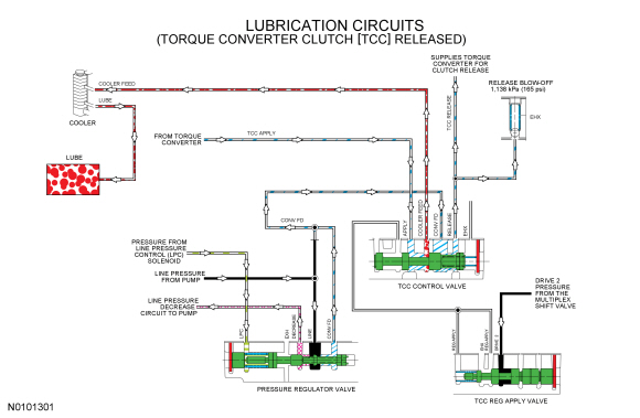
Lubrication Hydraulic Circuits
Lubrication for the transmission is supplied by the transmission fluid cooler return tube. Transmission fluid is sent to the transmission fluid cooler from the TCC control valve.
LINE pressure supplied to the pressure regulator valve is sent to the TCC control valve as CONV FD pressure. During TCC release, the TCC control valve sends the transmission fluid to the torque converter to release the clutch. The transmission fluid returns to the TCC control valve from the torque converter and is directed to the transmission fluid cooler on the COOLER FEED circuit.
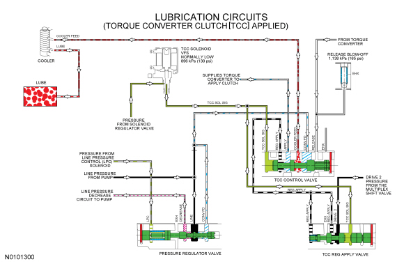
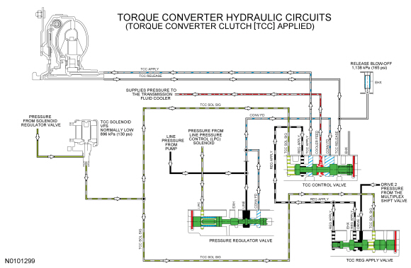
Torque Converter Hydraulic Circuits
The PCM controls the TCC solenoid. The TCC solenoid applies hydraulic pressure to the TCC control and regulator apply valves through the TCC SOL SIG circuit. Regulated DRIVE 2 pressure from the multiplex shift valve is directed to the TCC control valve by the TCC regulator apply valve through the REG APPLY circuit. The TCC control valve directs pressure from the REG APPLY circuit to the TCC APPLY circuit to apply the clutch.
The transmission fluid returns to the TCC control valve through the TCC RELEASE hydraulic circuit. The TCC control valve opens the TCC RELEASE circuit to exhaust, so the TCC RELEASE circuit is not pressurized when the TCC is applied.
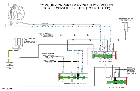
When the TCC is released, The TCC solenoid does not apply hydraulic pressure to the TCC control or regulator apply valves. The TCC control valve, in this position, directs hydraulic pressure from the CONV FD circuit to the torque converter through the TCC RELEASE hydraulic circuit and it returns to the TCC control valve through the TCC APPLY circuit.
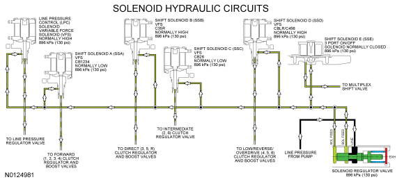
Solenoid Hydraulic Circuits
LINE pressure from the pump is directed to the individual shift, TCC and LPC solenoids by the solenoid regulator valve on the SOL FEED circuit. The solenoids, controlled by the PCM, direct the fluid to the valves that they control.
The LPC solenoid sends varying pressure to the line pressure regulator valve to control line pressure.
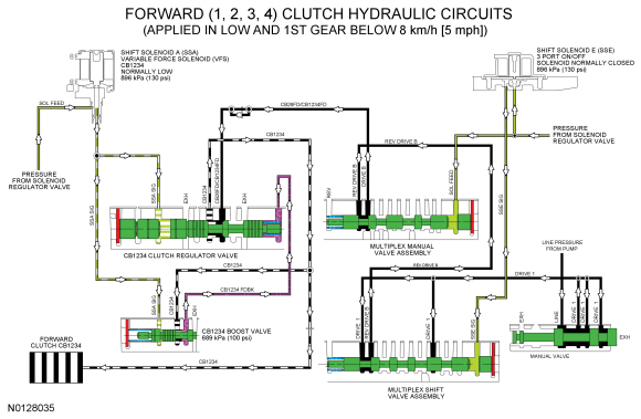
Forward Clutch Hydraulic Circuits
When the forward (1, 2, 3, 4) clutch is applied in 1st (above 8 kmh (5 mph), 2nd, 3rd and 4th gears, LINE pressure from the pump is directed to the multiplex shift valve by the manual valve through the DRIVE 1 hydraulic circuit. The multiplex shift valve supplies the forward (1, 2, 3, 4) clutch regulator valve with pressure through the DRIVE 2, CB26FD/CB1234FD and CB1234 SUP hydraulic circuits. The forward (1, 2, 3, 4) clutch regulator valve directs regulated pressure to the forward (1, 2, 3, 4) clutch through the CB1234 hydraulic circuit
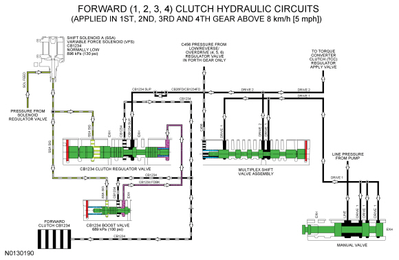
When the forward (1, 2, 3, 4) clutch is applied in LOW position and 1st gear below 8 kmh (5 mph), LINE pressure from the pump is directed to the multiplex shift valve by the manual valve through the DRIVE 1 hydraulic circuit. The multiplex shift valve directs the pressure to the multiplex manual valve through the REV DRIVE B circuit. The multiplex manual valve directs the REV DRIVE B pressure to the forward (1, 2, 3, 4) clutch regulator valve through the DRIVE B, CB26FD/CB1234FD and CB1234 SUP circuits. SSA supplies varying solenoid pressure to the CB1234 clutch regulator and boost valves. As the CB1234 clutch regulator valve moves, it supplies the forward (1, 2, 3, 4) clutch and CB1234 boost valve with regulated line pressure through the CB1234 circuit. The CB1234 boost valve directs the regulated line pressure to the opposite side of the regulator valve through the CB1234 FDBK circuit for controlled forward (1, 2, 3, 4) clutch engagement.
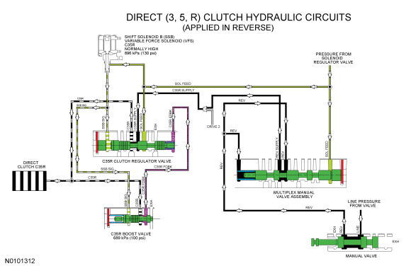
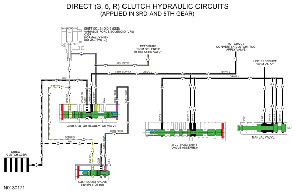
Direct (3, 5, R) Clutch Hydraulic Circuits
When the direct (3, 5, R) clutch is applied in REVERSE, LINE pressure from the pump is directed to the multiplex manual valve by the manual valve through the REV hydraulic circuit. The multiplex manual valve supplies the direct (3, 5, R) clutch regulator valve with pressure through the REV SUPPLY and C35R SUPPLY hydraulic circuits. To apply the direct (3, 5, R) clutch, SSB applies varying solenoid pressure to the C35R clutch regulator and boost valves. As the C35R regulator valve moves, it supplies the direct (3, 5, R) clutch and C35R boost valve with regulated line pressure through the C35R circuit. The C35R boost valve directs the regulated line pressure to the opposite side of the C35R clutch regulator valve through the C35R FDBK circuit for controlled direct (3, 5, R) clutch engagement.
When the direct (3, 5, R) clutch is applied in 3rd and 5th gears, LINE pressure from the pump is directed to the multiplex shift valve by the manual valve through the DRIVE 1 hydraulic circuit. The multiplex shift valve directs the pressure to the direct (3, 5, R) clutch regulator valve through the DRIVE 2/C35R SUPPLY circuits. To apply the direct (3, 5, R) clutch, SSB applies varying solenoid pressure to the C35R clutch regulator and boost valves. As the C35R regulator valve moves, it supplies the direct (3, 5, R) clutch and C35R boost valve with regulated line pressure through the C35R circuit. The C35R boost valve directs the regulated line pressure to the opposite side of the C35R clutch regulator valve through the C35R FDBK circuit for gradual direct (3, 5, R) clutch engagement.
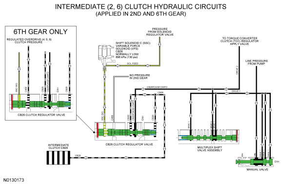
Intermediate (2, 6) Clutch Hydraulic Circuits
When the intermediate (2, 6) clutch is applied in 2nd and 6th gears, LINE pressure from the pump is directed to the multiplex shift valve by the manual valve through the DRIVE 1 hydraulic circuit. The multiplex shift valve supplies the intermediate (2, 6) clutch regulator valve with pressure through the DRIVE 2 and CB26FD/CB1234FD hydraulic circuits. The intermediate (2, 6) clutch regulator valve is controlled by SSC and directs regulated pressure to the intermediate (2, 6) clutch through the CB26 hydraulic circuit. The CB26 hydraulic circuit also supplies pressure to the opposite side of the CB26 clutch regulator valve for controlled intermediate (2, 6) clutch engagement. Regulated overdrive (4, 5, 6) clutch pressure is supplied to the intermediate (2, 6) clutch regulator valve in 6th gear to boost the SSC solenoid pressure.
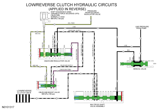
Low-Reverse Clutch Hydraulic Circuits
When the low-reverse clutch is applied in REVERSE, LINE pressure from the pump is directed to the multiplex shift valve by the manual valve through the REV hydraulic circuit to move the valve. Line pressure is also supplied to the low-reverse/overdrive clutch regulator valve from the pump. The low-reverse/overdrive clutch regulator valve is controlled by SSD and directs regulated pressure to the multiplex shift valve. The multiplex shift valve directs the regulated pressure to the low-reverse clutch through the CBLR SUPPLY circuit.
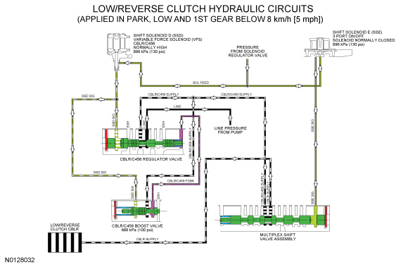
When the low-reverse clutch is applied in PARK, LOW or 1st gear below 8 kmh (5 mph), SSE pressure is supplied to the multiplex shift valve to move the valve. LINE pressure is supplied to the low-reverse/overdrive clutch regulator valve from the pump. The low-reverse/overdrive clutch regulator valve is controlled by SSD and directs regulated pressure to the multiplex shift valve. The multiplex shift valve directs the regulated pressure to the low-reverse clutch through the CBLR SUPPLY circuit.
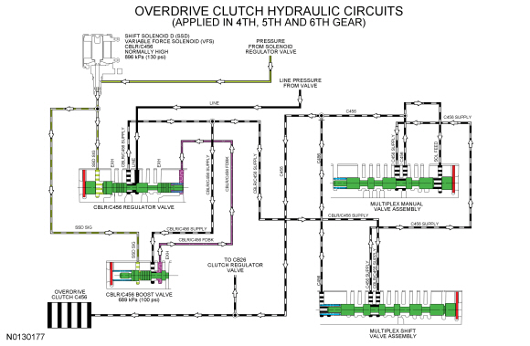
Overdrive Clutch Hydraulic Circuits
When the overdrive clutch is applied in 4th, 5th and 6th gears, LINE pressure is supplied to the low-reverse/overdrive (4, 5, 6) clutch regulator valve from the pump. To apply the overdrive (4, 5, 6) clutch, SSD applies varying solenoid pressure to the CBLR/C456 regulator and boost valves. As the CBLR/C456 regulator valve moves, it supplies the multiplex shift valve assembly and CBLR/C456 boost valve with regulated line pressure through the CBLR/C456 SUPPLY circuit. The CBLR/C456 boost valve directs the regulated line pressure to the opposite side of the CBLR/C456 regulator valve through the CBLR/C456 FDBK circuit for controlled overdrive (4, 5, 6) clutch engagement. The multiplex shift valve directs the regulated pressure to the multiplex manual valve through the C456 SUPPLY hydraulic circuit. The multiplex manual valve directs the regulated pressure to the overdrive (4, 5, 6) clutch through the C456 hydraulic circuit. The C456 circuit also supplies pressure to the CB26 clutch regulator valve to boost the pressure from SSC in 6th gear.
Mechanical System
Component Location
- Gear and shell assembly - front sun
- Front planetary carrier/rear planetary ring gear assembly
- Planetary carrier shell - front
- Carrier - front planetary
- Ring gear - rear planetary
- Gear - center planetary sun
- Center planetary carrier/front ring gear assembly
- Ring gear - front planetary
- Planetary carrier assembly - center
- Rear planetary carrier/center ring gear assembly
- Gear - center ring
- Carrier - rear planetary
- Gear - rear planetary sun
- Transmission Case
- Cover assembly
System Operation
System Diagram
Component Description
Planetary Gearset
This transmission has 3 planetary gearsets to provide operation in reverse and 6 forward speeds.
Front planetary gearset consists of the following components:
- Front planetary sun gear
- Front planetary carrier
- Front planetary ring gear
The front planetary sun gear is splined to the forward (1, 2, 3, 4) clutch and is held stationary in 1st, 2nd, 3rd and 4th gear.
The front planetary carrier is splined to the rear ring gear and transfers power from the rear planetary gearset to the front planetary gearset in 2nd, 3rd, 5th and 6th gear and reverse. The front planetary carrier is the output component for the planetary gearset as it is splined to the output hub.
The front planetary ring gear is splined to the center planetary carrier and transfers power from the center planetary gearset to the front planetary gearset in 1st, 2nd, 3rd and 4th gear.
Center planetary gearset consists of the following components:
- Center planetary sun gear
- Center planetary carrier
- Center planetary ring gear
The center planetary sun gear is splined to the input shaft and is used as input to the planetary gearsets in 1st, 2nd, 3rd, 4th and 5th gear.
The center planetary ring gear is splined to the rear planetary carrier. The center ring gear/rear planetary carrier is held stationary by the low OWC and low-reverse clutch in 1st gear and reverse. The center ring gear/rear planetary carrier is driven by the overdrive (4, 5, 6) clutch in 4th, 5th, and 6th gears.
Rear planetary gearset consists of the following components:
- Rear planetary ring gear
- Rear planetary carrier
- Rear planetary sun gear
The rear planetary carrier is splined to the overdrive (4, 5, 6) clutch hub and transfers power from the input shaft to the rear planetary carrier in 4th, 5th and 6th gear.
The rear planetary sun gear is splined to both the intermediate (2, 6) clutch and the direct (3, 5, R) clutch. The rear planetary sun gear is held stationary by the intermediate (2, 6) clutch in 2nd and 6th gear and is driven by the direct (3, 5, R) clutch in 3rd and 5th gear and reverse.
- Gear and shell assembly - front sun
- Front planetary carrier/rear planetary ring gear assembly
- Planetary carrier shell - front
- Carrier - front planetary
- Ring gear - rear planetary
- Gear - center planetary sun
- Center planetary carrier/front ring gear assembly
- Ring gear - front planetary
- Planetary carrier assembly - center
- Rear planetary carrier/center ring gear assembly
- Gear - center ring
- Carrier - rear planetary
- Gear - rear planetary sun
Input Shaft
The input shaft is part of the direct/overdrive clutch assembly and is splined to the torque converter turbine and the center planetary sun gear. The input shaft transfers power from the torque converter to the rear planetary gearset through the direct (3, 5, R) and overdrive (4, 5, 6) clutches and the center planetary sun gear.
- Input shaft (part of direct/overdrive clutch assembly)
- Direct clutch
- Overdrive clutch
- Center planetary sun gear
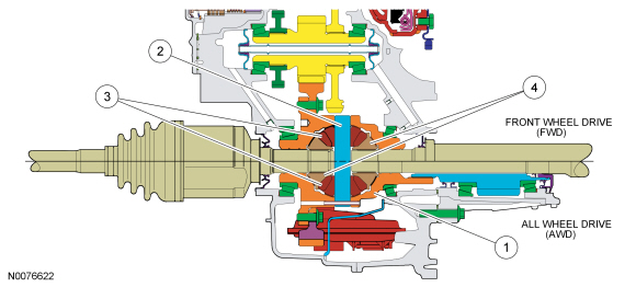
Front Planetary Carrier Hub (Output Hub)
The front planetary carrier hub is splined to the front planetary carrier and the transfer shaft drive gear. This allows torque to be transferred from the planetary gearset to the final drive gearset.
- Front planetary carrier
- Front planetary carrier hub
- Transfer shaft drive gear
Final Drive Gearset
The final drive consists of a gearset that transfers and multiplies torque from the planetary gearsets to the differential.
The final drive consists of the following components:
- Transfer shaft drive gear
- Transfer shaft and gear assembly
- Differential assembly
- Ring gear
The planetary gear set transfers power to the transfer shaft drive gear through the front planetary carrier hub. The transfer shaft drive gear is part of the stator support assembly. The transfer shaft drive gear turns the transfer shaft and gear assembly which multiplies torque through gear reduction and turns the differential ring gear.
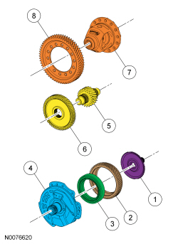
- Front planetary carrier hub
- Transfer shaft drive gear
- Transfer shaft drive gear bearing
- Stator support assembly
- Transfer shaft
- Transfer gear
- Differential assembly
- Differential ring gear
Differential
The differential allows the half shafts and wheels to rotate at different speeds during cornering and transfers power to the PTU for AWD vehicles. The differential assembly consists of the following components:
- Differential case (part of the final drive carrier)
- Two pinion gears supported by a pinion shaft
- Two side gears supported by the differential case and half shafts
When driving in a straight line, both front wheels rotate at relatively the same speed. This means both side gears are rotating at the same speed, as well, while both pinion gears revolve (but do not rotate) with the side gears. During cornering, the wheel on the outside of the turn is forced to rotate faster than the wheel on the inside of the turn. Since the side gears must now rotate at different speeds, the pinion gears rotate on the pinion shaft allowing the drive axles to rotate at different speeds while still transferring output torque.
- Differential housing
- Pinion shaft
- Pinion gears
- Side gears
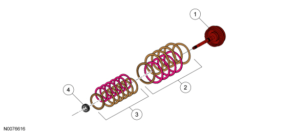
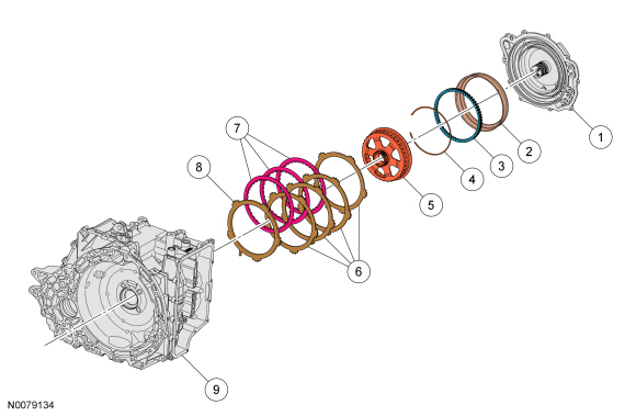
Forward (1, 2, 3, 4) Clutch
The forward clutch is a brake clutch that holds the front sun gear and shell assembly. The forward clutch is applied in 1st, 2nd, 3rd and 4th gear.
Hydraulic pressure from the regulator valve in the valve body pushes the forward clutch piston against the forward clutch pack to apply the clutch. The forward clutch pack is pushed against the low OWC when it is applied. The rear sun gear and shell assembly is held stationary to the transmission case as a result of the clutch being applied.
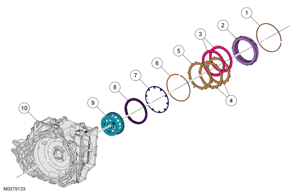
- Low OWC snap ring
- Low OWC
- Forward clutch friction plates
- Forward clutch steel plates
- Forward clutch waved cushion spring
- Forward clutch piston snap ring
- Forward clutch piston return spring
- Forward clutch piston
- Front sun gear and shell assembly
- Transmission case
Direct (3, 5, R) Clutch
The direct clutch is a drive clutch that transfers power from the direct/overdrive hub and shaft assembly to the rear sun gear. The direct clutch is applied in 3rd and 5th gear and reverse.
Hydraulic pressure from the regulator valve in the valve body pushes the direct clutch piston against the direct clutch pack to apply the clutch. The input shaft transfers torque to the rear planetary sun gear as a result of the clutch being applied.
- Snap ring - direct clutch cylinder
- Direct clutch cylinder
- Direct clutch piston
- Return spring - direct clutch piston
- Direct clutch piston seals
- Input shaft (part of direct/overdrive clutch assembly)
- Direct clutch friction plates
- Direct clutch wave spring
- Direct clutch steel plates
- Direct clutch pressure plate
- Direct clutch snap ring
- Rear planetary sun gear and shell assembly
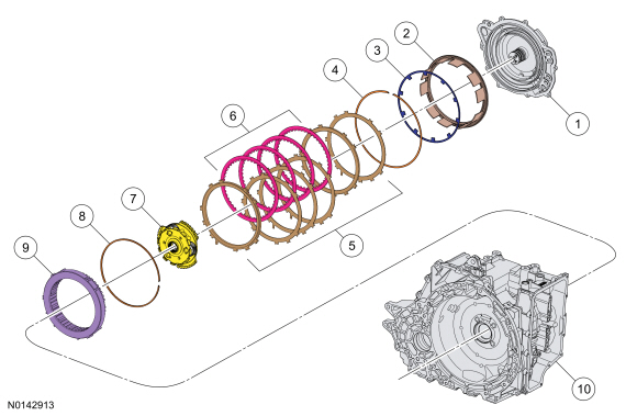
Intermediate (2, 6) Clutch
The intermediate clutch is a brake clutch that holds the rear sun and shell assembly. The intermediate clutch is applied in 2nd and 6th gear.
Hydraulic pressure from the regulator valve in the valve body pushes the intermediate clutch piston against the intermediate clutch pack to apply the clutch. The rear planetary sun gear is held stationary to the transmission case as a result of the clutch being applied.
- Cover assembly
- Intermediate clutch piston
- Intermediate clutch piston return spring
- Intermediate clutch piston return spring snap ring
- Rear planetary sun gear
- Intermediate clutch steel plates
- Intermediate clutch friction plates
- Intermediate clutch pressure plate
- Transmission case
Low-Reverse Clutch
The low/reverse clutch is a brake clutch that holds the low OWC which is splined to the rear planetary carrier. The low/reverse clutch is applied in manual LOW, REVERSE and 1st gear up to 8 kmh (5 mph).
Hydraulic pressure from the regulator valve, routed through the multiplex shift valve in the valve body, pushes the low/reverse clutch piston against the low/reverse clutch pack to apply the clutch. The rear planetary carrier is held stationary to the transmission case as a result of the clutch being applied.
- Cover assembly
- Low/reverse clutch piston
- Low/reverse clutch piston return spring
- Low/reverse clutch return spring snap ring
- Low/reverse clutch steel plates
- Low/reverse clutch friction plates
- Rear planetary carrier
- Low OWC snap ring
- Low OWC
- Transmission case
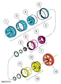
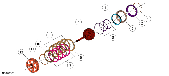
Overdrive Clutch
The overdrive clutch is a drive clutch that transfers power from the direct/overdrive hub and shaft assembly to the rear planetary carrier. The overdrive clutch is applied in 4th, 5th and 6th gear.
Hydraulic pressure from the regulator valve in the valve body pushes the overdrive clutch piston against the overdrive clutch pack to apply the clutch. The input shaft transfers torque to the rear planetary sun gear as a result of the clutch being applied.
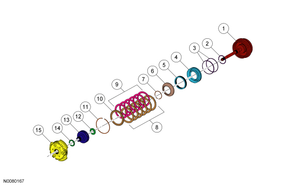
- Input shaft (part of direct/overdrive clutch assembly)
- Overdrive clutch piston inner seal
- Overdrive clutch piston outer seals
- Overdrive clutch piston
- Overdrive clutch piston return spring
- Overdrive clutch balance piston
- Overdrive clutch balance piston snap ring
- Overdrive clutch steel plates
- Overdrive clutch friction plates
- Overdrive clutch pressure plate
- Overdrive clutch snap ring
- Overdrive clutch hub thrust bearing
- Overdrive clutch hub
- Rear sun gear thrust bearing
- Rear planetary carrier
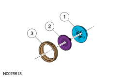
Low One-Way Clutch
The low OWC is a brake clutch that holds the rear planetary carrier in one direction and allows it to freewheel in the opposite direction which eliminates engine braking in 1st gear when the transmission is in DRIVE. The low OWC is used in 1st gear when the transmission is in DRIVE.
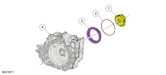
- Rear planetary carrier
- Low OWC snap ring
- Low OWC
- Transmission case

 Diagnosis and Testing
Automatic Transmission
Special Tool(s)
Material
DTC Chart
Diagnostics in this manual assume a certain skill level and knowledge of
Ford-specific diagnostic practices. Refer to Diagnostic Methods in ...
Other materials:
Accessories
For a complete listing of the accessories that are available for your
vehicle, please contact an authorized dealer or visit our online store at
www.Accessories.Ford.com (United States only).
Ford Motor Company will repair or replace any properly authorized
dealer-installed Ford Genuine Accesso ...
Export unique (non–united states/canada) vehicle
specific information
For your particular global region, your vehicle may be equipped with
features and options that are different from the features and options that
are described in this owner’s manual. A market unique supplement may
be supplied that complements this book. By referring to the market
unique supplem ...
Cleaning the windows and wiper blades
The windows and wiper blades should be cleaned regularly. If the wipers
do not wipe properly, substances on the vehicle’s glass or the wiper
blades may cause squeaking or chatter noise from the blades, and
streaking and smearing of the windshield. To clean these items, follow
these tips:
• ...
