SPECIFICATIONS
Material
Torque Specifications
DESCRIPTION AND OPERATION
Rear Drive Axle and Differential
The rear drive axle consists of the following components:
- Dished circular flange
- Full-time Active Torque Coupling (ATC)
- Aluminum housing with steel housing cover
- Matched ring and pinion
- Conventional open differential
- Rubber bushing isolated mounting points
- Cover-mounted axle vent
The rear axle drive pinion receives power from the engine through the transaxle, Power Transfer Unit (PTU), driveshaft and ATC, and is always engaged. The All-Wheel Drive (AWD) system on this vehicle is equipped with a bar-coded rear axle to reduce the tolerance of electrical current-to-torque delivered by the ATC. The 4X4 control module uses this bar code information to match the clutch characteristics of the ATC with the desired output torque. The pinion gear then rotates the differential ring gear, which is bolted to the differential case outer flange. Inside the differential case, 2 differential pinion gears are mounted on a differential pinion shaft, which is pinned to the differential case. These differential pinion gears are engaged with the differential side gears to which the halfshafts are splined. The halfshafts are held in the differential case by a driveshaft bearing retainer circlip that is located on the inboard CV joint stub shaft pilot bearing housing. When each halfshaft is installed, the driveshaft bearing retainer circlip engages a step in the differential side gear. As the differential case turns, it rotates the halfshafts and rear wheels. When it is necessary for one wheel and halfshaft to rotate faster than the other, the faster turning differential side gear causes the differential pinion gears to roll on the slower turning differential side gear. This allows differential action between the 2 halfshafts. The pinion seal and the differential halfshaft seals are the only serviced components of the rear drive axle. There are no stub shaft bearings in the differential housing and the differential housing cover uses a silicone sealant rather than a gasket. If other components of the rear drive axle or the ATC are worn or damaged, a new axle assembly must be installed.
IN-VEHICLE REPAIR
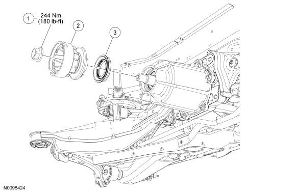
Drive Pinion Seal
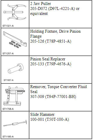
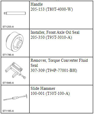
Special Tool(s)
Material
Removal
- Remove the driveshaft. For additional information, refer to Section 205-01.
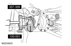
- Using the Drive Pinion Flange Holding Fixture, hold the pinion flange
and remove the nut.
- Discard the nut.
- Index-mark the location of the pinion to the yoke.
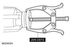
- Using the 2 Jaw Puller, remove the pinion flange.
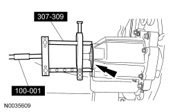
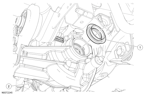
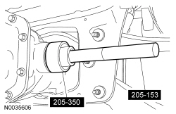
- Using the Torque Converter Fluid Seal Remover and Slide Hammer, remove the seal.
Installation
- NOTE: Make sure that the mating surface is clean before
installing the new seal.
Using the Pinion Seal Replacer, install the seal.
- NOTE: Lubricate the pinion flange with grease.
Line up the index marks and position the pinion flange.

- Using the Drive Pinion Flange Holding Fixture, install the new pinion
nut.
- Tighten to 244 Nm (180 lb-ft).

- Install the driveshaft. For additional information, refer to Section 205-01.
Stub Shaft Seal
Special Tool(s)
Material
Removal
NOTE: The Rear Drive Unit (RDU) does not have stub shaft pilot bearings. It has stub shaft seals only.
- Remove the halfshaft assembly. For additional information, refer to Section 205-05.
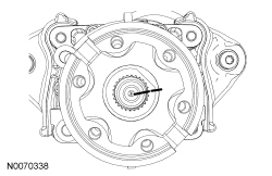
- Using the Torque Converter Fluid Seal Remover and Slide Hammer, remove the stub shaft seal.
Installation
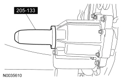
- NOTE: Lubricate the new stub shaft seal with grease.
Using the Front Axle Oil Seal Installer and Handle, install the stub shaft pilot bearing housing seal.
- Install the halfshaft assembly. For additional information, refer to Section 205-05.
Differential Housing Cover
Material
Removal
- With the vehicle in NEUTRAL, position it on a hoist. For additional information, refer to Section 100-02.
- If equipped, remove the exhaust insulator located near the differential housing cover using soapy water.
- NOTE: Drain the differential fluid into a suitable drain pan.
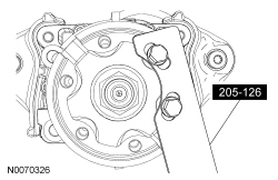
Remove the 10 bolts and the rear differential housing cover.
- Drain the differential fluid from the housing.
Installation
- NOTE: Make sure the machined surfaces on the rear axle housing
and the differential housing cover are clean and free of oil before
installing the new silicone sealant. The inside of the rear axle must be
covered when cleaning the machined surface to prevent contamination.
Clean the gasket mating surfaces of the differential housing and the differential housing cover.
- NOTE: The differential housing cover must be installed within 15
minutes of application of the silicone, or new silicone must be applied. If
possible, allow one hour before filling with lubricant to make sure the
silicone has correctly cured.
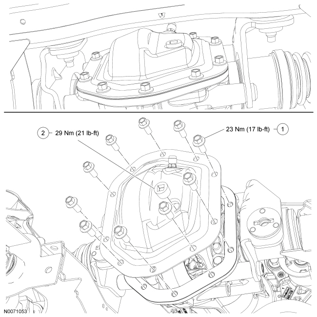
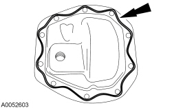
Apply a new continuous bead of clear silicone rubber as shown in the illustration.
- Install the differential housing cover and the 10 bolts.
- Tighten to 23 Nm (17 lb-ft).
- Remove the filler plug and fill the rear axle with 1.15L (2.43 pt) of
rear axle lubricant, 3-5 mm (0.118-0.196 in) below the bottom of the filler
hole.
- Install the filler plug and tighten to 29 Nm (21 lb-ft).
- If equipped, install the exhaust insulator located near the differential housing cover.
REMOVAL AND INSTALLATION
Axle Assembly
Special Tool(s)
Removal
- Remove the driveshaft assembly. For additional information, refer to Section 205-01.
- Remove the rear halfshafts. For additional information, refer to Section 205-05.
- Remove the stabilizer bar. For additional information, refer to Section 204-02.
- Position a suitable transmission hydraulic jack to the axle housing.
- Securely strap the jack to the housing.
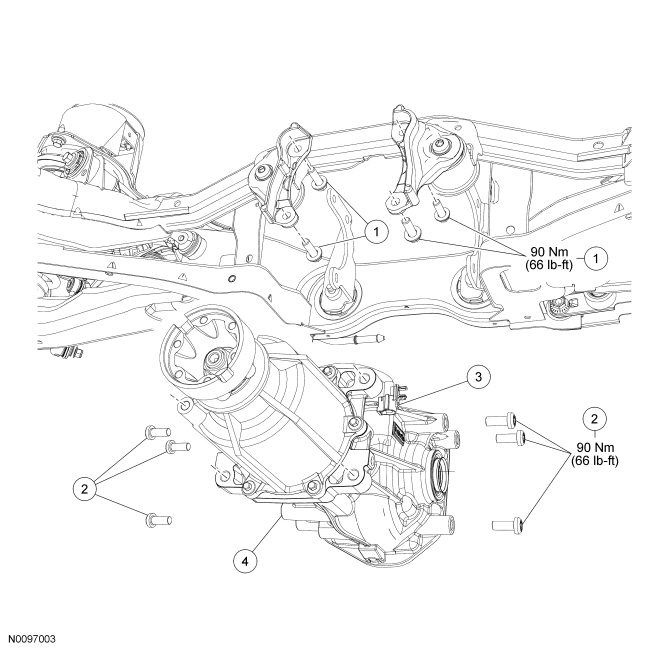
- Remove the 4 differential housing-to-front insulator bracket bolts.
- Remove the 6 side insulator bracket-to-rear axle differential bolts.
- Lower the axle to gain clearance to the Active Torque Coupling (ATC) electrical connector and disconnect the connector.
- Remove the axle assembly.
Installation
- NOTICE: If replacing the axle assembly, the 4X4 control module
will need to be reconfigured with the new Active Torque Coupling (ATC) bar
code information. If the new bar code information does not match the
existing 4X4 control module information, driveline damage or driveability
concerns can occur.
NOTE: The ATC bar code can be found etched on the ATC wire harness connector of the new axle assembly.
Record the bar code identification number from the new axle assemblies wire harness connector.

- Position the axle housing on a suitable transmission hydraulic jack.
- Securely strap the jack to the housing.
- Raise the axle and connect the ATC electrical connector.
- Install the 6 side insulator bracket-to-rear axle differential bolts.
- Tighten to 90 Nm (66 lb-ft).
- Install the 4 differential housing-to-front insulator bracket bolts.
- Tighten to 90 Nm (66 lb-ft).
- Install the stabilizer bar. For additional information, refer to Section 204-02.
- Install the rear halfshafts. For additional information, refer to Section 205-05.
- Install the driveshaft assembly. For additional information, refer to Section 205-01.
- If a new RDU was installed, re-configure the Automatic Torque Coupling (ATC). Refer to Section 308-07A.
 Driveshaft
SPECIFICATIONS
Torque Specifications
DESCRIPTION AND OPERATION
Driveshaft
NOTE: All driveshaft assemblies are balanced. If undercoating the
vehicle, protect the driveshaft to prevent overspra ...
 Front Drive Halfshafts
SPECIFICATIONS
Torque Specifications
a Refer to the procedure in this section.
DESCRIPTION AND OPERATION
Front Drive Halfshafts
The halfshafts consist of the following components:
Inner C ...
Other materials:
Anti-Theft - Passive Anti-Theft System (PATS), Without Intelligent Access (IA)
DESCRIPTION AND OPERATION
Anti-Theft
Overview
PATS deters the vehicle from theft by preventing the engine from starting
unless a programmed PATS key is in the ignition. PATS does not disable an
already running engine.
System Operation
System Diagram
Network Message Chart
...
Heated seats
WARNING: Persons who are unable to feel pain to the skin
because of advanced age, chronic illness, diabetes, spinal cord
injury, medication, alcohol use, exhaustion, or other physical conditions,
must exercise care when using the seat heater. The seat heater may
cause burns even at low temperatu ...
Engine Ignition - 2.0L GTDI
SPECIFICATIONS
Material
General Specifications
Torque Specifications
DESCRIPTION AND OPERATION
Engine Ignition
Component Location
System Operation
REFER to the PC/ED manual
section 1 Description and Operation.
Component Description
REFER to the PC/ED manual
section ...
