SPECIFICATIONS
Torque Specifications
a Refer to the procedure in this section.
DESCRIPTION AND OPERATION
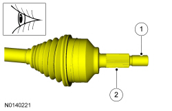
Front Drive Halfshafts
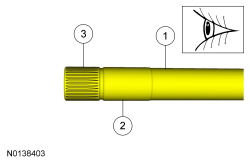
The halfshafts consist of the following components:
- Inner CV joints
- Outer CV joints
- Interconnecting shafts
The halfshafts are splined on the outboard stub shaft to drive the wheel hubs. They are retained in the wheel hubs by special wheel hub nuts which also control the wheel bearing preload. The LH halfshaft is splined on the inboard stub shaft and is retained in the differential side gear in the transaxle by a circlip. The circlips must be installed new whenever they are removed. The RH halfshaft is retained in the transaxle differential side gear by bolts that go through the intermediate shaft support bearing. The intermediate shaft also goes through the Power Transfer Unit (PTU) on All-Wheel Drive (AWD) vehicles. The outer seal of the PTU must be installed new whenever the RH halfshaft is removed.
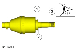
Halfshaft Joint
The front drive halfshaft CV joints consist of the following components:
- CV joint boot clamps
- Convoluted CV joint boots
- Tripod joint housings
- Ball and cage housings
- Retainer circlips
- Special CV high-temperature grease
The CV joint mates the interconnecting shaft with the stub shaft. The joint allows for smooth rotation of the interconnecting shaft and the stub shafts. They also adjust for length variances and angle requirements as the vehicle goes through jounce and rebound.
The halfshaft joints are not repairable and are serviced as assemblies only.
Halfshaft Handling
Handle all halfshaft components carefully during removal and installation and during various component disassembly and assembly procedures.
- Never pick up or hold the halfshaft only by the inboard or outboard CV joint.
- Do not overangle the CV joints.
- Damage will occur to an assembled inboard CV joint if it is overplunged outward from the joint housing.
- Never use a hammer to remove or install the halfshafts from the front hub.
- Never use the halfshaft assembly as a lever to position other components. Always support the free end of the halfshaft.
- Do not allow the boots to contact sharp edges or hot exhaust components.
- Handle the halfshaft only by the interconnecting shaft to avoid pull-apart and potential damage to the CV joints.
- Excessive pulling force on the interconnecting shaft between joints of the halfshaft will result in internal joint damage. Axial loads used in assisting removal must be applied through the inboard joint housing only.
- Do not drop assembled halfshafts. The impact will cut the boots from the inside without evidence of external damage.
- Do not remove the outer CV joint by pulling on the interconnecting shaft.
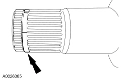
- Inspect all machined surfaces and splines for damage.
- Do not allow the ball joint stud to contact the CV joint boot when disconnecting the lower arm.
REMOVAL AND INSTALLATION
Halfshaft - RH
Removal
All vehicles
- With the vehicle in NEUTRAL, position it on a hoist. For additional information, refer to Section 100-02.
- Remove the wheel and tire. For additional information, refer to Section 204-04.
- Discard the specified component. Follow local disposal regulations.
- Discard the specified component. Follow local disposal regulations.
- NOTICE: Suspension fasteners are critical parts because they
affect performance of vital components and systems and their failure may
result in major service expense. New parts must be installed with the same
part number or equivalent part, if replacement is necessary. Do not use a
replacement part of lesser quality or substitute design. Torque values must
be used as specified during reassembly to make sure of correct retention of
these parts.
NOTICE: Use care when releasing the lower arm and knuckle into the resting position or damage to the ball joint seal or Constant Velocity (CV) boot may occur.
NOTE: Use the hex-holding feature to prevent the stud from turning while removing the nut.
Discard the specified component. Follow local disposal regulations.
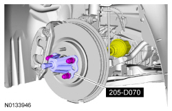
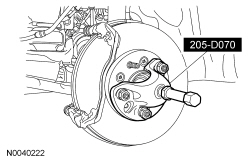
- Special Tool(s): Remover, Front Wheel Hub 205-D070
All Vehicles except 3.5L Gasoline Turbocharged Direct Injection (GTDI) and Police Vehicles
Vehicles with 3.5L GTDI and Police Vehicles
- Discard the specified component. Follow local disposal regulations.
Installation
AWD vehicles
NOTICE: A new Power Transfer Unit (PTU) shaft seal must be installed whenever the intermediate shaft is removed or damage to the components can occur.
- Install a new intermediate shaft seal and deflector. For additional information, refer to Section 308-07B.
All vehicles
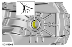
- Visual check
FWD vehicles
- Visual check
AWD vehicles
- Visual check
Vehicles with 3.5L GTDI and Police Vehicles
All Vehicles except 3.5L GTDI and Police Vehicles
-
- Tighten to 25 Nm (18 lb-ft).

All vehicles
-
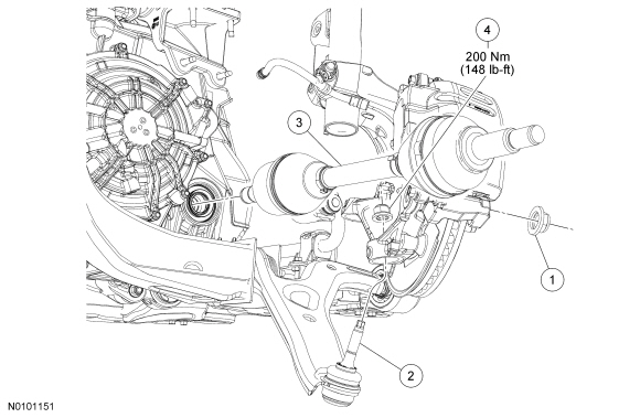
- Tighten to 200 Nm (148 lb-ft).
-
- Tighten to 150 Nm (111 lb-ft).
-
- Tighten to 150 Nm (111 lb-ft).
- NOTICE: Do not tighten the front wheel hub nut with the
vehicle on the ground. The nut must be tightened to specification before the
vehicle is lowered onto the wheels. Wheel bearing damage will occur if the
wheel bearing is loaded with the weight of the vehicle applied.
Using the previously removed wheel hub nut, seat the halfshaft.
- Tighten to 350 Nm (258 lb-ft).

- Discard the specified component. Follow local disposal regulations.
- NOTICE: The wheel hub nut contains a one-time locking chemical
that is activated by the heat created when it is tightened. Install and
tighten the new wheel hub nut to specification within 5 minutes of starting
it on the threads. Always install a new wheel hub nut after loosening or
when not tightened within the specified time or damage to the components can
occur.
- Tighten to 350 Nm (258 lb-ft).

- Install the wheel and tire. For additional information, refer to Section 204-04.
Halfshaft - LH
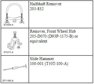
Special Tool(s)
Exploded View
Removal
- With the vehicle in NEUTRAL, position it on a hoist. For additional information, refer to Section 100-02.
- Remove the wheel and tire. For additional information, refer to Section 204-04.
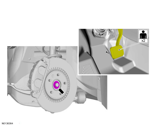
- NOTE: Apply the brake to keep the halfshaft from rotating.
Remove the wheel hub nut.
- Do not discard at this time.
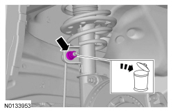
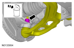
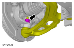
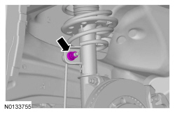
- NOTICE: Use care when releasing the lower arm and knuckle into
the resting position or damage to the ball joint seal or Constant Velocity
(CV) boot may occur.
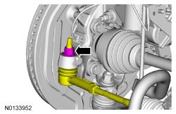
NOTE: Use the hex-holding feature to prevent the stud from turning while removing the nut.
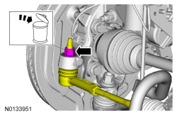
Remove and discard the lower ball joint nut.- Separate the ball joint from the wheel knuckle.
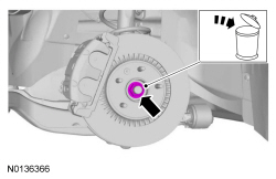
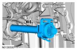
- Using the Front Wheel Hub Remover, separate the halfshaft from the wheel hub.
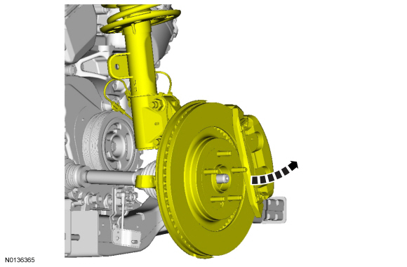
- Pull the wheel knuckle outboard and rotate it toward the rear of the vehicle.
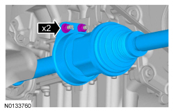
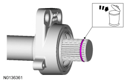
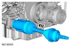
- NOTICE: The sharp edges on the stub shaft splines can slice or
puncture the oil seal. Use care when inserting the stub shaft into the
transmission or damage to the component may occur.
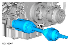
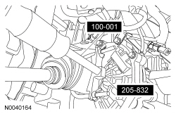
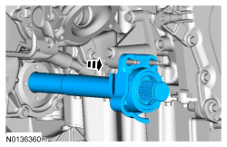
Using the Slide Hammer and Halfshaft Remover, remove the halfshaft from the transmission.
- Remove and discard the circlip from the stub shaft.

Installation
Vehicles equipped with 6F35
- NOTICE: If the LH transmission case bushing or the LH
halfshaft bushing surface shows signs of excessive wear or damage, a new LH
transmission case bushing and a new LH halfshaft must be installed, or
excessive noise or transmission failure can occur.
Inspect the Transaxle Case Bushing. If the surface is damaged, Refer to Section 307-01B.
All
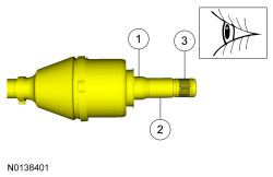
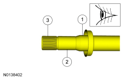
- Inspect the inboard halfshaft hub surfaces for wear or damage and install a new halfshaft, if necessary.
- Inspect the outboard halfshaft hub surfaces for wear or damage and install a new halfshaft, if necessary.
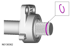
- NOTICE: The circlips are unique in size and shape for each
shaft. Make sure to use the specified circlip for the application or vehicle
damage may occur.
Install the correct new circlip on the inboard stub shaft.
- NOTE: After insertion, pull the halfshaft inner end to make sure
the circlip is locked.
Push the stub shaft into the transmission so the circlip locks into the differential side gear.
- Rotate the wheel knuckle into position and insert the halfshaft into the wheel hub.
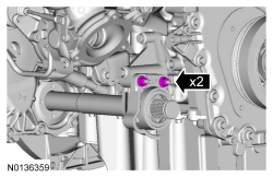
- Position the lower ball joint into the wheel knuckle and install the new
nut.
- Tighten the new nut to 200 Nm (148 lb-ft).
- NOTICE: Do not tighten the wheel hub nut with the vehicle on
the ground. The nut must be tightened to specification before the vehicle is
lowered onto the wheels. Wheel bearing damage will occur if the wheel
bearing is loaded with the weight of the vehicle applied.
NOTE: Apply the brake to keep the halfshaft from rotating.
Using the previously removed wheel hub nut, seat the halfshaft.- Tighten to 350 Nm (258 lb-ft).
- Remove and discard the wheel hub nut.
- NOTICE: The wheel hub nut contains a one-time locking chemical
that is activated by the heat created when it is tightened. Install and
tighten the new wheel hub nut to specification within 5 minutes of starting
it on the threads. Always install a new wheel hub nut after loosening or
when not tightened within the specified time or damage to the components can
occur.
NOTE: Apply the brake to keep the halfshaft from rotating.
Install a new wheel hub nut.- Tighten to 350 Nm (258 lb-ft).
- Install the front wheel and tire. Refer to Section 204-04.
Intermediate Shaft - 3.5L GTDI
Removal
NOTICE: The intermediate shaft seal in the Power Transfer Unit (PTU) must be replaced whenever the intermediate shaft is removed or a leak may occur. For additional information, refer to Section 308-07B.
- Remove the right halfshaft assembly. For additional information, refer to Halfshaft - RH in this section.

- Discard the specified component. Follow local disposal regulations.

Installation
- Install a new 30 mm (1.181 in) circlip on the outboard end of the intermediate shaft.

- Install a new intermediate shaft seal in the Power Transfer Unit (PTU). For additional information, refer to Section 308-07B.
-
- Tighten to 25 Nm (18 lb-ft).
- Install the right halfshaft. For additional information, refer to Halfshaft - RH in this section.
 Rear Drive Axle/Differential
SPECIFICATIONS
Material
Torque Specifications
DESCRIPTION AND OPERATION
Rear Drive Axle and Differential
The rear drive axle consists of the following components:
Dished circular flange
Full-t ...
 Rear Drive Halfshafts
SPECIFICATIONS
Torque Specifications
a Refer to the procedure in this section.
DESCRIPTION AND OPERATION
Rear Drive Halfshafts
The halfshafts consist of the following components:
Inner CV ...
Other materials:
General Procedures
Audio Control Module (ACM) Self-Diagnostic Mode
NOTE: If the ACM is completely inoperative (does not power up), the
part number decal on the ACM chassis can be used to attain the ACM part number.
Turn the ACM on.
Operate the audio system in radio tu ...
Parking Aid - Audible
SPECIFICATIONS
General Specifications
DESCRIPTION AND OPERATION
Parking Aid
Component Location
Parking aid speaker
PAM
Parking aid sensors
Overview
The parking aid system sounds a warning to alert the driver of stationary
objects near the rear bumper when REVERSE is selected. The rear sensor ...
Starting a gasoline engine
When you start the engine, the idle speed increases, this helps to warm
up the engine. If the engine idle speed does not slow down automatically,
have your vehicle checked by an authorized dealer.
Note: You can crank the engine for a total of 60 seconds (without the
engine starting) before the ...
