SPECIFICATIONS
General Specifications
DESCRIPTION AND OPERATION
Parking Aid
Component Location
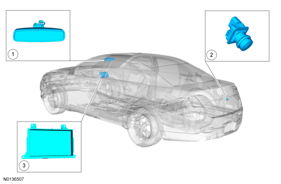
Overview
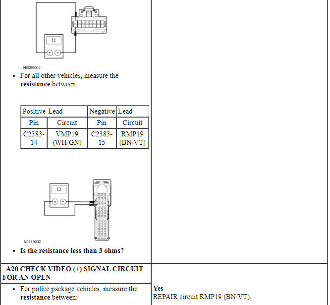
The video camera system visually aids the driver while reversing or reverse parking the vehicle. For police package vehicles, the image of the area behind the vehicle is displayed in the LH side of the auto-dimming interior mirror assembly. For all other vehicles, the image of the area behind the vehicle is displayed in the FDIM. The video camera system is controlled though the FDIM. There are no camera controls on police package vehicles. Refer to the Owner's Literature for operating the video camera system features.
System Operation
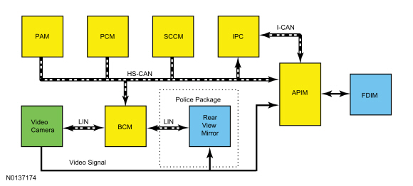
System Diagram
Network Message Chart
Module Network Input Messages - BCM
Module Network Input Messages - APIM
Image Display - Police Package
The decklid must remain closed for correct operation of the video camera system.
The video camera system has 2 video features:
- Fixed guidelines - this feature assists the driver with backing into a parking space or aligning the vehicle with an object.
- Video camera delay - this feature allows the driver to see the image behind the vehicle after the vehicle is shifted out of REVERSE. The image will not be displayed if the vehicle is shifted into PARK.
The video camera delay feature is controlled within the rear view mirror. The video camera delay feature keeps the image displayed on the rear view mirror until the vehicle reaches 8 kmh (5 mph) when the vehicle is shifted out of REVERSE. The video camera fixed guidelines feature displays guidelines on top of the video image to assist the driver with alignment of the vehicle. The guidelines are only available when the transmission is in REVERSE. Three color-coded lines (red, yellow, green) identify different zones between the rear of the vehicle and objects.
The color-coded lines cannot indicate accurate or consistent distances between objects located behind the vehicle and at the rear of the vehicle. This normal condition is due to variances in vehicle ride height, including, but not limited to, vehicle loading.
The BCM and the video camera communicate on a LIN, which is a dedicated single wire communication network.
The messages sent from the BCM to the video camera are:
- Transmission selector (PRNDL) status (REVERSE/no REVERSE only)
- Decklid ajar status
- Camera configuration data
- Parking aid audible warning status
- Parking aid sensor distance to object data
The messages sent from the video camera to the BCM are:
- Camera status
- Camera part number data
- Visual park aid alert status
- Fixed guideline status
Image Display - Except Police Package
The decklid must remain closed for correct operation of the video camera system.
The video camera system has 5 video features that are controlled in the FDIM :
- Fixed guidelines - this feature assists the driver with backing into a parking space or aligning the vehicle with an object.
- Active guidelines - this feature projects the intended path of the vehicle based upon steering wheel input.
- Visual park aid alert - this feature assists the driver to visually see the object causing the parking aid system to sound.
- Manual zoom - this feature assists the driver with connecting or towing a trailer allowing the driver to manually zoom closer to an object behind the vehicle.
- Video camera delay - this feature allows the driver to see the image behind the vehicle after the vehicle is shifted out of REVERSE. The image will not be displayed if the vehicle is shifted into PARK.
For each one of these system features except the camera delay feature, the BCM sends backup camera commands to the video camera. The video camera delay feature is set in the FDIM and controlled by the APIM.
All of the video camera features are enabled and disabled within the FDIM menu screen. The video camera delay feature keeps the image displayed on the FDIM until the vehicle reaches 8 kmh (5 mph) when the vehicle is shifted out of REVERSE or if any button on the FDIM is pressed. The video camera fixed guidelines feature displays guidelines on top of the video image to assist the driver with alignment of the vehicle. A dashed line on the displayed image represents the center of the vehicle and 3 color-coded lines (red, yellow, green) identify different zones between the rear of the vehicle and objects.
The color-coded lines cannot indicate accurate or consistent distances between objects located behind the vehicle and at the rear of the vehicle. This normal condition is due to variances in vehicle ride height, including, but not limited to, vehicle loading.
The manual zoom feature is controlled by the video camera. The manual zoom feature has 3 zoom levels in the FDIM that are only active when the vehicle is in REVERSE. If the manual zoom feature is enabled and the vehicle is shifted out of REVERSE, the manual zoom feature is disabled. The manual zoom feature must be re-enabled the next time the vehicle is shifted into REVERSE.
The BCM and the video camera communicate on a LIN, which is a dedicated single wire communication network.
The messages sent from the BCM to the video camera are:
- Transmission selector (PRNDL) status (REVERSE/no REVERSE only)
- Decklid ajar status
- Camera configuration data
- Display manual zoom request
- Parking aid audible warning status
- Parking aid sensor distance to object data
The messages sent from the video camera to the BCM are:
- Camera status
- Display zoom status
- Camera part number data
- Visual park aid alert status
- Fixed guideline status
Visual Park Aid
The visual park aid alert feature utilizes the 4 parking aid sensor inputs from the PAM and the video camera image. When the transmission selector is in REVERSE and an object is detected in the path of the parking aid sensor, parking aid range to object data is sent from the PAM through the BCM to the video camera.
The visual alerts are red, yellow or green and appear as highlights on top of the displayed image to indicate in which zone the object is detected. The highlighted visual alerts are still operational if the parking aid system is disabled within the IPC and the visual alert feature is enabled.
Active guidelines display the intended vehicle path based upon the steering wheel angle.
Component Description
Video Camera
The rear video camera system is active with the ignition in RUN and the transmission selector in REVERSE. The video camera receives commands and sends status over a dedicated LIN to the BCM. The video camera is programmable and is configured through the BCM using a scan tool. The video camera configuration can be performed using a scan tool under Body > RVC configuration.
DIAGNOSIS AND TESTING
Parking Aid
DTC Charts
Diagnostics in this manual assume a certain skill level and knowledge of Ford-specific diagnostic practices. Refer to Diagnostic Methods in Section 100-00 for information about these practices.
APIM DTC Chart
BCM DTC Chart
Symptom Chart
Diagnostics in this manual assume a certain skill level and knowledge of Ford-specific diagnostic practices. Refer to Diagnostic Methods in Section 100-00 for information about these practices.
Pinpoint Tests
Pinpoint Test A: The Rear Video Is Inoperative
Diagnostic Overview
Diagnostics in this manual assume a certain skill level and knowledge of Ford-specific diagnostic practices. Refer to Diagnostic Methods in Section 100-00 for information about these practices.
Refer to Wiring Diagrams Cell 131, Parking Aid for schematic and connector information.
Normal Operation and Fault Conditions
REFER to Image Display in Parking Aid.
BCM DTC Fault Trigger Conditions
APIM DTC Fault Trigger Conditions
-
Possible Sources
- Fuse
- Wiring, terminals or connectors
- Video camera
- BCM
- APIM
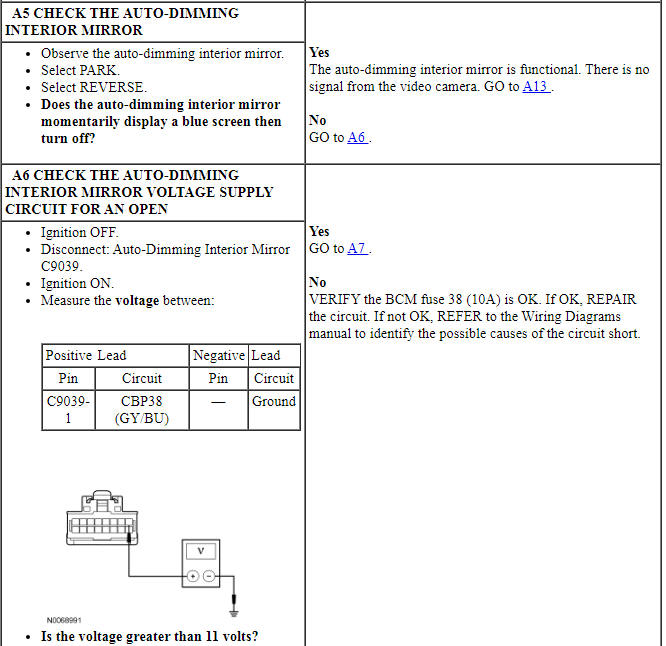
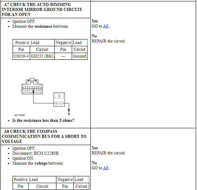
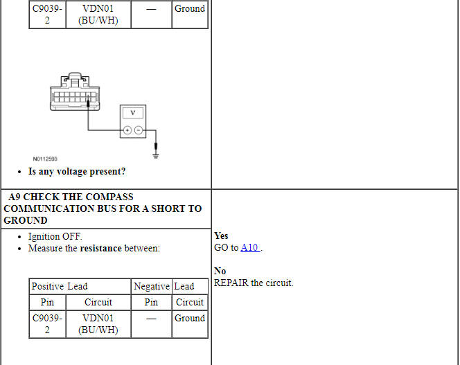
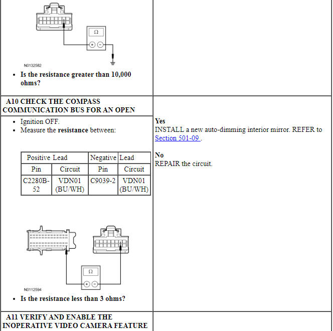
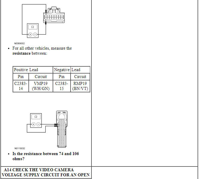
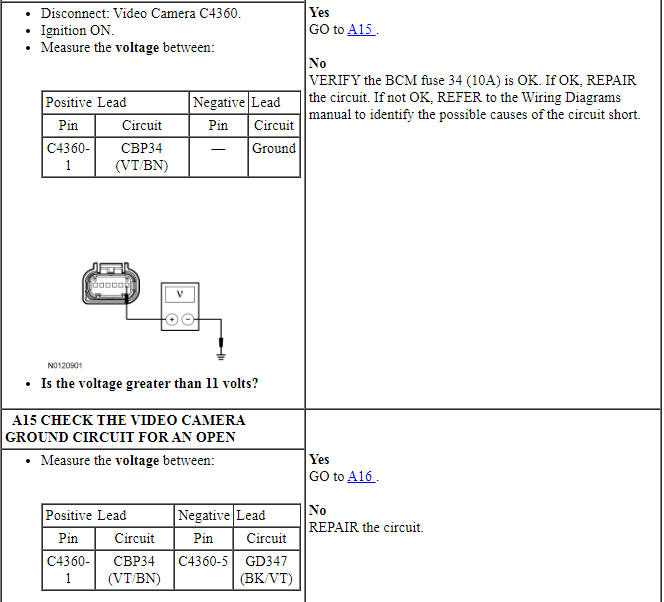
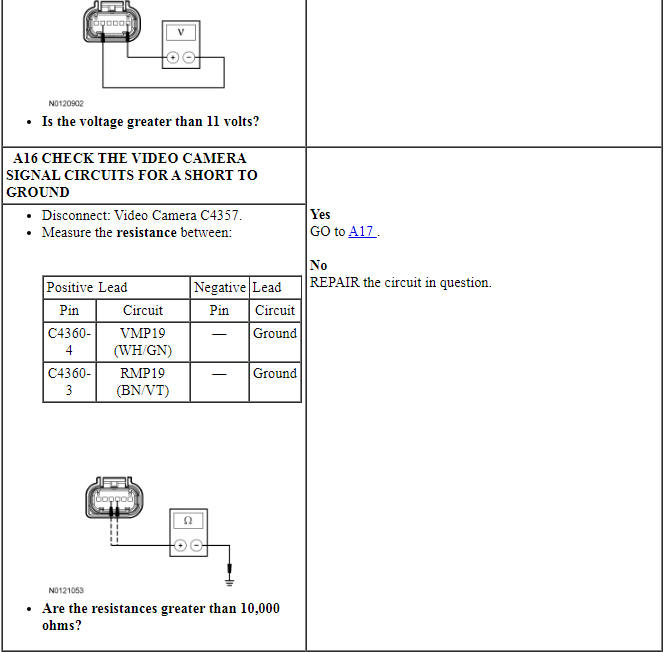
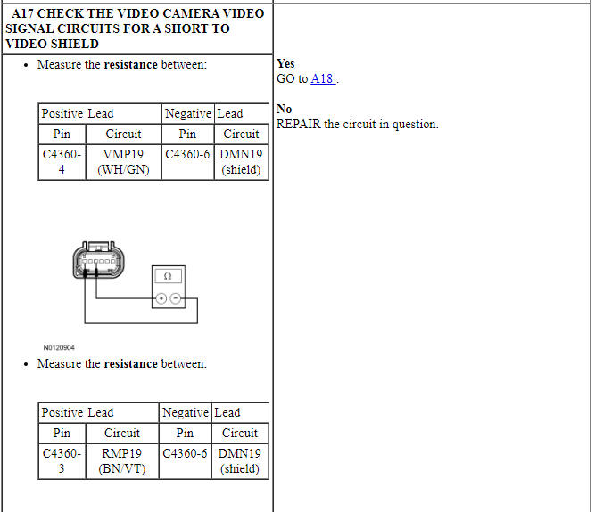
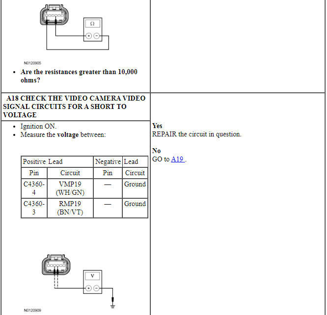
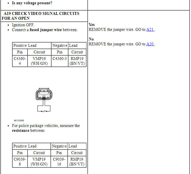
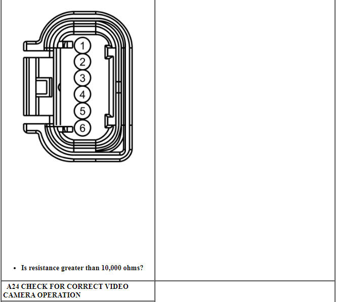
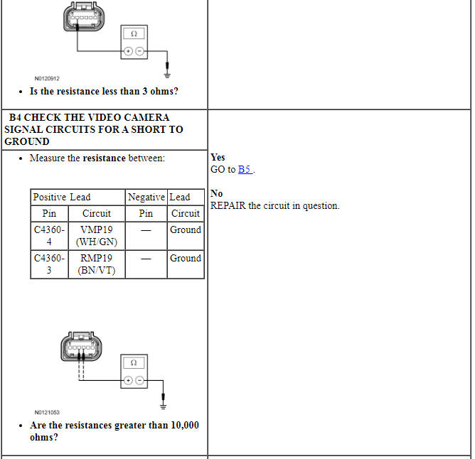
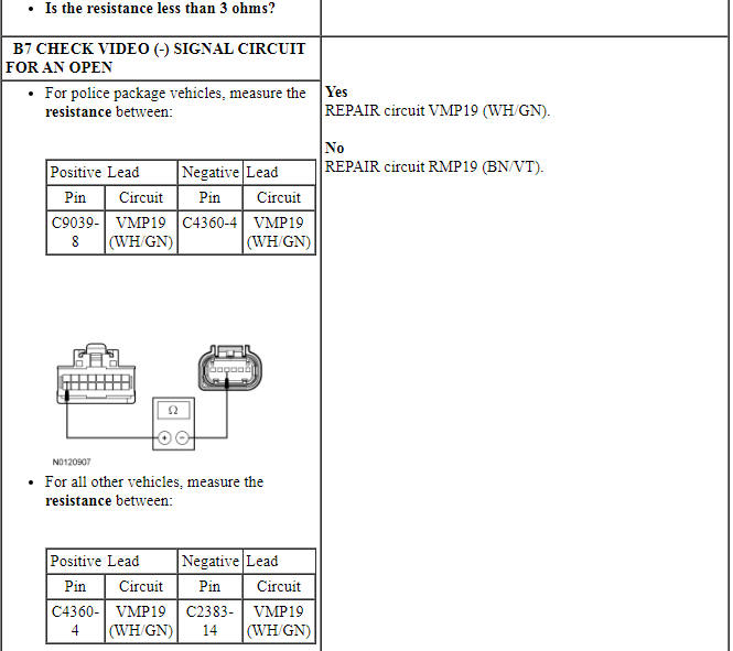
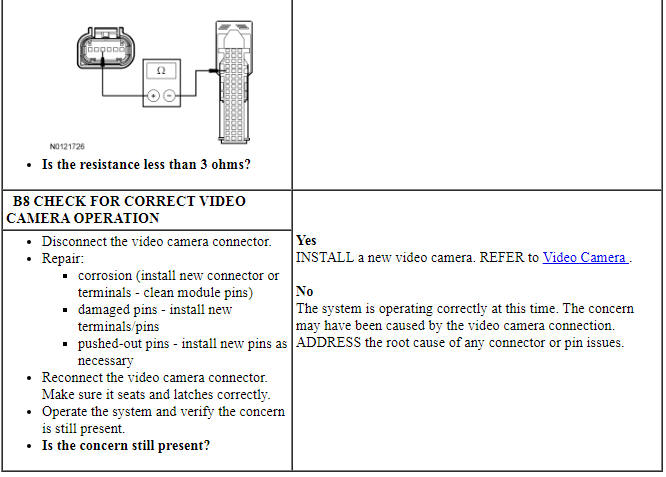
PINPOINT TEST A: THE REAR VIDEO IS INOPERATIVE
NOTICE: Use the correct probe adapter(s) when making measurements. Failure to use the correct probe adapter(s) may damage the connector.
NOTE: Failure to disconnect the battery when instructed results in false resistance readings. Refer to Section 414-01.
Pinpoint Test B: Poor Image Quality
Diagnostic Overview
Diagnostics in this manual assume a certain skill level and knowledge of Ford-specific diagnostic practices. Refer to Diagnostic Methods in Section 100-00 for information about these practices.
Refer to Wiring Diagrams Cell 131, Parking Aid for schematic and connector information.
Normal Operation and Fault Conditions
REFER to Image Display in Parking Aid.
-
Possible Sources
- Wiring, terminals or connectors
- Video camera
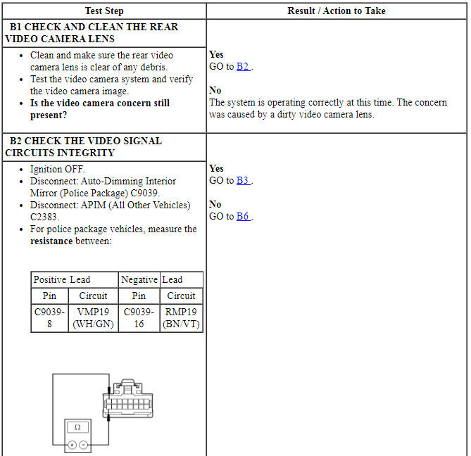
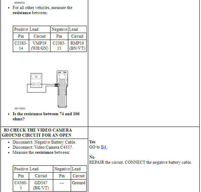
PINPOINT TEST B: POOR IMAGE QUALITY
NOTICE: Use the correct probe adapter(s) when making measurements. Failure to use the correct probe adapter(s) may damage the connector.
NOTE: Failure to disconnect the battery when instructed results in false resistance readings. Refer to Section 414-01.
Pinpoint Test C: Visual Park Aid Is Inoperative
Diagnostic Overview
Diagnostics in this manual assume a certain skill level and knowledge of Ford-specific diagnostic practices. Refer to Diagnostic Methods in Section 100-00 for information about these practices.
Refer to Wiring Diagrams Cell 131, Parking Aid for schematic and connector information.
Normal Operation and Fault Conditions
REFER to Visual Parking Aid in Parking Aid.
-
Possible Sources
- Video camera
- PAM
- BCM
PINPOINT TEST C: VISUAL PARK AID IS INOPERATIVE
NOTICE: Use the correct probe adapter(s) when making measurements. Failure to use the correct probe adapter(s) may damage the connector.
Pinpoint Test D: The Video Guidelines Are Inoperative
Diagnostic Overview
Diagnostics in this manual assume a certain skill level and knowledge of Ford-specific diagnostic practices. Refer to Diagnostic Methods in Section 100-00 for information about these practices.
Refer to Wiring Diagrams Cell 131, Parking Aid for schematic and connector information.
Normal Operation and Fault Conditions
REFER to Image Display in Parking Aid.
REFER to Visual Parking Aid in Parking Aid.
-
Possible Sources
- Fixed guidelines feature is disabled
- Video camera
PINPOINT TEST D: THE VIDEO GUIDELINES ARE INOPERATIVE
NOTICE: Use the correct probe adapter(s) when making measurements. Failure to use the correct probe adapter(s) may damage the connector.
REMOVAL AND INSTALLATION
Video Camera
Removal
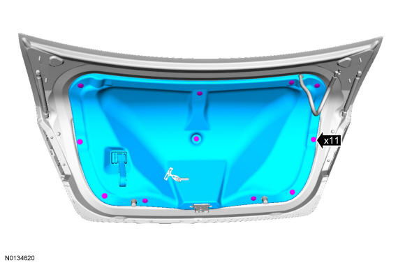
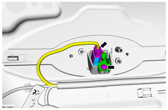
Installation
- To install, reverse the removal procedure.
- Configure the rear video camera following the instructions on the scan tool.
 Parking Aid - Audible
SPECIFICATIONS
General Specifications
DESCRIPTION AND OPERATION
Parking Aid
Component Location
Parking aid speaker
PAM
Parking aid sensors
Overview
The parking aid system sounds a warning to al ...
 Active Park Assist
SPECIFICATIONS
General Specifications
DESCRIPTION AND OPERATION
Active Park Assist
Component Location
Active park assist sensor
Active park assist switch
Parking aid module
Overview
The active ...
Other materials:
Auxiliary Power Points
WARNING: Do not plug optional electrical accessories into the
cigarette lighter socket (if equipped). Improper use of the lighter
can cause damage not covered by your warranty, and can result in fire
or serious injury.
Note: If used when the engine is not running, the battery will
discharge.
...
Collision Avoidance
DESCRIPTION AND OPERATION
Forward Collision Warning
Overview
The forward collision warning system alerts the driver of a collision risk
with a red warning LED indicator bar located above the instrument panel (part of
the HUD module) and an audible warning chime from the IPC. The
AB ...
Transmission fluid check
6F35 TRANSMISSION (if equipped)
Note: Transmission fluid should be checked by an authorized dealer.
If required, fluid should be added by an authorized dealer.
The automatic transmission does not have a transmission fluid dipstick.
Refer to your scheduled maintenance information for schedu ...
