Sectioning Guidelines
General Equipment
Material
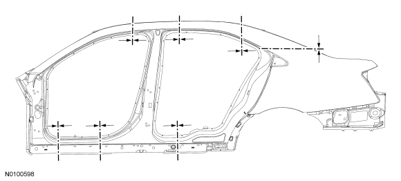
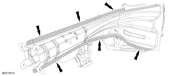
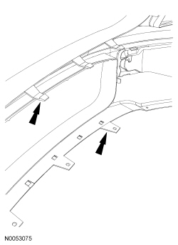
NOTE: The following illustration provides recommended sectioning points. Cut lines shown in illustration are approximate.
WARNING: Collision damage repair must conform to the instructions contained in this workshop manual. Replacement components must be new, genuine Ford Motor Company parts. Recycled, salvaged, aftermarket or reconditioned parts (including body parts, wheels or safety restraint components) are not authorized by Ford.
Departure from the instructions provided in this manual, including alternate repair methods or the use of substitute components, risks compromising crash safety. Failure to follow these instructions may adversely affect structural integrity and crash safety performance, which could result in serious personal injury to vehicle occupants in a crash.
WARNING: Invisible ultraviolet and infrared rays emitted in welding can injure unprotected eyes and skin. Always use protection such as a welder's helmet with dark-colored filter lenses of the correct density. Electric welding will produce intense radiation, therefore, filter plate lenses of the deepest shade providing adequate visibility are recommended. It is strongly recommended that persons working in the weld area wear flash safety goggles. Also wear protective clothing. Failure to follow these instructions may result in serious personal injury.
WARNING: Always wear protective equipment including eye protection with side shields, and a dust mask when sanding or grinding. Failure to follow these instructions may result in serious personal injury.
WARNING: On vehicles equipped with Safety Canopy options, prior to carrying out any sectioning repairs near the roof line or sail panel areas of the vehicle, remove the Safety Canopy module and related components. Failure to comply may result in accidental deployment or damage to the Safety Canopy. Refer to Section 501-20B. Failure to follow these instructions may result in serious injury to technician or vehicle occupant(s).
WARNING: Do not cut or grind body side components within 50 mm (1.96 in) of restraint anchoring points. Welding within 50 mm (1.96 in) of restraint anchoring points may result in incorrect operation of restraint devices. For additional restraints anchoring location information, refer to Section 501-20A and Section 501-20B. Failure to follow these instructions may result in serious injury to vehicle occupant(s).
NOTICE: Electronic modules and related wiring may be damaged when exposed to heat from welding procedures. Carefully disconnect and remove, or position away from heat affected areas.
NOTE: Observe prescribed welding procedures when carrying out any body side section repair. For additional information, refer to Welding Precautions - Steel in this section.
NOTE: When it is necessary to carry out weld-bonding procedures, refer to Weld-Bonding in this section.
NOTE: Factory spot welds may be substituted with either resistance spot welds or Metal Inert Gas (MIG) plug welds. Spot/plug welds should equal factory welds in both location and quantity. Do not place a new spot weld directly over an original weld location. Plug weld hole should equal 8 mm (0.31 in) diameter.
- Detrim the vehicle and protect surfaces adjacent to the repair area.
- Drill out the spot welds of the damaged panel to be sectioned. Using a cut-off wheel, reciprocating saw or plasma cutter, cut through the damaged area of the outer panel only and remove the section to be replaced.
- Make sure horizontal joints and flanges are correctly sealed with seam sealer to prevent moisture intrusion. Water and moisture migrate to horizontal joints and corrosion tends to occur more rapidly in these areas. Metal surfaces must be clean and dry before applying seam sealer.
- When welding overlapping surfaces or substrates, apply a weld-through primer to the surfaces prior to welding. When the surfaces have been welded, apply corrosion protection material to the interior and exterior surfaces or substrates. For additional information, refer to Restoring Corrosion Protection Following Repair in this section.
- Proceed with the refinish process following Ford-approved paint guidelines.
Restoring Corrosion Protection Following Repair
Special Tool(s)
Material
WARNING: Always refer to Material Safety Data Sheet (MSDS) when handling chemicals and wear protective equipment as directed. Examples may include but are not limited to respirators and chemically resistant gloves. Failure to follow these instructions may result in serious personal injury.
WARNING: Always wear protective equipment including eye protection with side shields, and a dust mask when sanding or grinding. Failure to follow these instructions may result in serious personal injury.
NOTICE: Drilling access holes in body panels is not recommended. Drilling holes will break the original paint finish and promote corrosion.
NOTE: Corrosion protection needs to be restored whenever it is necessary to sand or grind through painted surfaces or E-coat, or when bare metal repairs are made.
NOTE: Refer to product label for preparation and handling instructions.
- The surfaces must be free of oil, dirt and other foreign material. Carry
out the process in the following sequence.
- Thoroughly clean and degrease metal surfaces using metal surface prep to remove wax and grease.
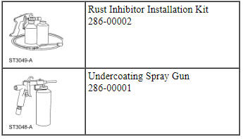
- For best results, the vehicle should be at room temperature. Attach the rust inhibitor canister to the Rust Inhibitor Installation Kit 286-00002.
- Rust inhibitor should be applied after the welding and refinishing process. Product cannot be welded through.
- Air pressure setting for applicator gun is 448-517 kPa (65-75 psi).
- Use the long wand when spraying enclosed areas. The spray nozzle provides a 360-degree spray pattern. Insert the wand as far as possible into the access hole, pull the trigger and wait 2-3 seconds and slowly pull the wand out of the access hole.
- The short, hook-shaped wand sprays in one direction and must be rotated to provide complete coverage.
- Apply the material in light mist coats.
- Material displaces moisture.
- Clean up any overspray with a mild solvent such as mineral spirits or bug and tar remover.
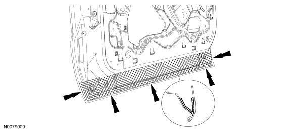
NOTE: The following illustrations provide typical applications of body seams and spot welded flanges and are not vehicle specific.
- NOTE: Door assembly lower view.
Apply rust inhibitor as shown to the inside of the door shell on all the interior metal surfaces using the most suitable applicator wand. Apply material to the exposed edges after carrying out the welding process. Make sure horizontal surfaces are well protected as they are more susceptible to corrosion. Keep door drain holes clear to prevent moisture buildup.
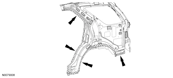
- NOTE: Quarter panel inner view.
Apply rust inhibitor to the closed channel portion of the spot weld flange areas using the short, hook-shaped wand. Apply material to the exposed edges after carrying out the welding process. Make sure horizontal surfaces are well protected as they are more susceptible to corrosion.
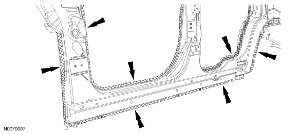
- NOTE: Door frame opening view.
Apply rust inhibitor to the closed channel portion of the spot weld flange areas using the short, hook-shaped wand. Make sure horizontal surfaces are well protected as they are more susceptible to corrosion.
Body and Frame Undercoating
- WARNING:
Always refer to Material Safety Data Sheet (MSDS) when handling chemicals
and wear protective equipment as directed. Examples may include but are not
limited to respirators and chemically resistant gloves. Failure to follow
these instructions may result in serious personal injury.
WARNING: Always wear protective equipment including eye protection with side shields, and a dust mask when sanding or grinding. Failure to follow these instructions may result in serious personal injury.
NOTICE: Do not allow undercoating on powertrain components. Failure to follow these instructions may result in incorrect operation of these components.
NOTE: Refer to product label for preparation and handling instructions.
NOTE: Avoid high-pressure water spray cleaning to treated underbody area for 24 hours.
Wire brush the area and make sure the surfaces are free of oil, dirt and other foreign material. Carry out the undercoating process in the following sequence.- Thoroughly clean and degrease metal surfaces using metal surface prep to remove wax and grease.
- For best results, the vehicle should be at room temperature.
- Canister attaches directly to the dispensing gun. Attach the undercoating canister to the Undercoating Spray Gun 286-00001.
- Undercoat should be applied after the welding and refinishing process. Product cannot be welded through.
- Air pressure setting for applicator gun is 552-621 kPa (80-90 psi).
- Apply light mist coats, applicator sprays in fogging pattern.
- Material displaces moisture.
- Clean up any overspray with a mild solvent such as mineral spirits or bug and tar remover.
NOTE: The following illustrations provide typical applications to frame rails and are not vehicle specific.
- NOTE: Frame rail exterior spot-weld flange view.
Apply undercoat material to the exterior exposed edges after carrying out the welding and refinishing process.
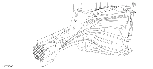
- NOTE: Cross section view of typical unibody frame rail shown.
Apply rust inhibitor to the inner surfaces of the rail after carrying out welding process. Use the long wand and insert as far as possible, depress trigger and wait 2-3 seconds and slowly pull the wand to make sure the area is completely fogged.
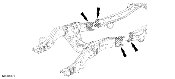
- NOTE: Full frame vehicle, front rail-to-mid rail section repair
shown.
Apply undercoat material to the exposed surfaces after carrying out the welding process. Make sure to completely cover any bare metal areas.
Refinishing - Environmental Damage
Material
Iron Oxide (Rail Dust) or Acid Rain Decontamination
WARNING: Always refer to Material Safety Data Sheet (MSDS) when handling chemicals and wear protective equipment as directed. Examples may include but are not limited to respirators and chemically resistant gloves. Failure to follow these instructions may result in serious personal injury.
WARNING: Always wear protective equipment including eye protection with side shields, and a dust mask when sanding or grinding. Failure to follow these instructions may result in serious personal injury.
NOTICE: In extreme cases of contamination, the vehicle may require refinishing. To avoid paint failure, follow the appropriate decontamination procedure prior to carrying out any panel refinishing procedure.
NOTE: Iron oxide contamination appears as tiny rust spots on horizontal surfaces and in severe cases can be felt. This damage is typically caused from rail shipment, storage near railroad tracks or fallout from industrial manufacturing facilities.
NOTE: Acid rain contamination can be identified as water spotting and, in severe cases, staining within the water spots.
- NOTICE: Never paint over iron particles as rust spots will
reoccur. Use only the recommended decontamination procedure detailed below.
Rinse any dust, dirt and foreign material from the vehicle body with cold water. Flush liberally.
- Prepare the acid neutralizer by mixing 8 parts of water to 1 part neutralizer in a bucket.
- NOTICE: To avoid paint failure, do not allow the product to
dry on the vehicle.
NOTE: Use a separate wash mitt for each product applied to the vehicle.
Working quickly and beginning at the top of the vehicle and working to the sides, apply the acid neutralizer mix to the entire vehicle. Keep the vehicle wet with the solution and lightly agitate for 5 to 7 minutes. Continue around the vehicle 4 to 5 times. For severe conditions, work the product for up to 8 minutes.
- Rinse the vehicle completely with cold water to remove the product.
- Dry only the horizontal surfaces of the vehicle, do not dry the glass at this time.
- NOTICE: To avoid damage to the paint surface, do not apply the
alkaline neutralizer directly to the vehicle plastic trim.
NOTE: Use a separate wash mitt for each product applied to the vehicle.
NOTE: Alkaline neutralizer is a ready-to-use product. Do not mix with water.
Pour the alkaline neutralizer into a squirt bottle and apply the solution to a clean wash mitt.
- NOTICE: To avoid paint failure, do not allow the alkaline
neutralizer to dry on the vehicle.
Apply the product to the vehicle keeping the solution wet and lightly agitate for 5 to 7 minutes. For severe conditions, work the product for up to 8 minutes.
- Rinse the vehicle completely with cold water to remove the product.
- Prepare the detail wash by mixing 29.5 ml (1 oz) with 3.78L (1 gal) of water.
- Using a clean wash mitt, shampoo the entire vehicle and rinse with cold water. Dry the vehicle completely.
- Visually inspect the paint surface for any remaining evidence of ferrous metal particles. Repeat procedure as necessary.
Surface Finishing Following Decontamination
- NOTICE: When attempting to affect a repair by buffing,
polishing or color sanding, do not remove an excess of 0.3 mil of paint film
or refinishing will be required.
NOTE: Acid rain discoloring or etching may require color sanding in addition to buffing and polishing. In extreme cases, refinishing may be required if the following procedure does not restore the vehicle finish.
NOTE: Do not intermix buffing products. Use only one manufacturer's product.
NOTE: Always follow the manufacturer's product usage sequence. Use the appropriate buffing or polishing pad at the recommended buffing speed as specified by the product manufacturer.
Apply rubbing compound to the vehicle surface as recommended by the product manufacturer.
- Apply machine glaze to the vehicle surface as recommended by the product manufacturer.
- Use an alcohol and water mixture (1 to 1) to clean the buffed and polished areas. Verify removal of scratches and swirls before the application of the final polish.
- Apply a final polish material by hand, with a dual-action sander and foam pad, or with an orbital polisher and appropriate polishing bonnet.
- Wash and dry the vehicle.
Refinishing - Manufacturing Damage
Material
WARNING: Always refer to Material Safety Data Sheet (MSDS) when handling chemicals and wear protective equipment as directed. Examples may include but are not limited to respirators and chemically resistant gloves. Failure to follow these instructions may result in serious personal injury.
WARNING: Always wear protective equipment including eye protection with side shields, and a dust mask when sanding or grinding. Failure to follow these instructions may result in serious personal injury.
NOTICE: To avoid overspray damage to adjacent panels, protect adjacent areas/substrates when preparing for and during refinishing.
NOTE: Peeling/delamination concerns can be described as lack of adhesion, either between the substrate and topcoats or between individual coats of paint.
- Wash the repair area with detail wash or pH-neutral soap and water.
- Remove any trim, emblems and hardware from the area to be repaired.
- NOTE: All delamination must be removed.
Sand or media blast the damaged surface, keeping the repair area as minimal as possible.
- Treat any bare metal surface to prevent flash corrosion, and prime and block sand as necessary prior to refinishing.
- Mask the adjacent panels to protect from overspray.
- Spot repair the base coat as necessary, following the paint manufacturer's prescribed procedures.
- Following the paint manufacturer's prescribed procedure, apply clear coat to the entire panel.
Plastics Identification
WARNING: Always refer to Material Safety Data Sheet (MSDS) when handling chemicals and wear protective equipment as directed. Examples may include but are not limited to respirators and chemically resistant gloves. Failure to follow these instructions may result in serious personal injury.
WARNING: Always wear protective equipment including eye protection with side shields, and a dust mask when sanding or grinding. Failure to follow these instructions may result in serious personal injury.
NOTE: Identification of the various plastic types is necessary to select the appropriate repair methods to make high quality plastic repairs. Plastics can generally be broken down into 2 categories, thermoplastics and thermosetting plastics. Thermoplastics can be remolded by heating. This makes plastic welding a possible repair alternative.
- NOTE: In some instances, a code or material designation is
stamped indicating the plastic type.
Thermoplastics are solvent reactive. Types of thermoplastics include Thermoplastic Olefin (TPO), Polyvinyl Chloride (PVC) and Acrylonitrile Butadiene Styrene (ABS). Polyolefins have an oily or waxy appearance. Examples include some bumper covers, stone shields, fender aprons and fan shrouds. Polyolefins require an adhesion promoter prior to carrying out any refinish procedure.
- To determine if the part is a polyolefin, grind the damaged area in an out-of-sight area. Grinding a polyolefin will melt and smear the plastic and leave a ragged edge. If the part is non-polyolefin, the area will grind or sand smoothly, producing a powdery dust.
Rigid Plastic Parts
Flexible Plastic Parts
- Polyolefin plastic can also be identified by placing a small sliver in a container of water, if the sample floats, it is a polyolefin plastic. A non-polyolefin will sink when placed in a container of water.
- Generally, thermosetting plastics are rigid or semi-rigid. Sheet-Molded
Composite (SMC) is reinforced with glass and other fibers and are strong and
rigid. SMC is used for large panels such as hoods, liftgates, fenders and
quarter panels.
- A burn test can be a reliable method to determine if a plastic is a
thermosetting plastic. Extreme care must be exercised when using this
method.
- NOTICE: The component must be isolated away from the
vehicle and all combustible materials to perform this test.
Apply an open flame to the corner of the damaged component. If the material crystallizes and becomes hard, it is a thermosetting plastic.
- NOTICE: The component must be isolated away from the
vehicle and all combustible materials to perform this test.
- A burn test can be a reliable method to determine if a plastic is a
thermosetting plastic. Extreme care must be exercised when using this
method.
Plastics Refinishing
All Components
WARNING: Always refer to Material Safety Data Sheet (MSDS) when handling chemicals and wear protective equipment as directed. Examples may include but are not limited to respirators and chemically resistant gloves. Failure to follow these instructions may result in serious personal injury.
WARNING: Do not paint any airbag trim covers or deployment doors. Paint may cause the airbag to deploy incorrectly. Failure to follow this instruction may increase the risk of serious personal injury or death in a crash.
NOTE: When using any Ford-approved refinishing product, it is recommended to stay within the same paint system throughout the process. For example, do not use one manufacturer's primers and another manufacturer's topcoats.
- NOTE: Care must be used if applying heat to parts. Thermoplastics
soften and tend to lose their shape when heated.
The first step for any repair or refinish procedure is to identify the type of plastic. Is it thermosetting or thermoplastic, grained or smooth? This will determine how it should be cleaned and prepared for refinishing. For additional information, refer to Plastics Identification in this section.
- It is essential that the correct cleaner is used, depending on which painting system is employed, solvent-based or water-based.
- Clean part with warm water/mild detergent, then with plastic cleaner to remove wax, silicone and other contaminants. Do not allow parts to remain wet for extended periods.
- As a general rule, if water beads on the part, it requires additional cleaning as all the manufacturing release agents have not been removed.
- New parts may require baking in a spray booth or heating with heat lamps to release trapped solvents or mold release agents used in the manufacturing processes.
Non-grained components
- After cleaning, lightly sand with 600-grit or finer sandpaper. Remove sanding residue with plastic cleaner and wipe dry.
Grained components
- After cleaning, light use of a gray scuff pad is permissible providing the graining not be flattened. Remove sanding residue with plastic cleaner and wipe dry.
All components
- Apply a plastics adhesion promoter to any bare plastic part following manufacturer's recommendation. Throughout the refinish procedure, any time bare plastic is exposed for any reason, it is essential that adhesion promoter be reapplied to that area.
- A sealer may be required to prevent wrinkling and lifting of the topcoat prior to carrying out the refinish procedure.
- Flexible and non-flexible components should be refinished separately as a flex additive may be required when refinishing flexible parts (refer to the paint manufacturer's recommendation).
- It is recommended to carry out refinishing of exterior components on-vehicle (after cut-in) to control color match and blending to adjacent panels.
- Proceed with the refinish process and follow the Ford-approved paint system procedures. Steps may vary between paint manufacturers.
Plastics Repair
Material
WARNING: Always wear protective equipment including eye protection with side shields, and a dust mask when sanding or grinding. Failure to follow these instructions may result in serious personal injury.
WARNING: Always refer to Material Safety Data Sheet (MSDS) when handling chemicals and wear protective equipment as directed. Examples may include but are not limited to respirators and chemically resistant gloves. Failure to follow these instructions may result in serious personal injury.
- In deciding whether to repair or install a new component, follow these
guidelines.
- Is a part readily available?
- Can the damaged part be economically returned to its original strength and appearance, or will the labor cost exceed the cost of a new component?
- Will repair provide for the fastest, highest quality repair?
- NOTICE: Never apply solvents such as lacquer thinner or
reducer at any stage of plastic repair. Solvents, cleaners and water are
absorbed by many types of plastics and by the glass fibers used for
reinforcements. If this occurs, the plastic may swell in the area of repair
and cause the repair to fail. Remove cleaners and water quickly and use air
and heat to speed up drying.
NOTICE: During the repair of many plastics and particularly polyolefin plastics, an adhesion promoter must be applied to the substrate to allow repair materials and paint to bond correctly. Reapplication is required when grinding or sanding through the sealer or primered layers.
NOTE: When possible, it is recommended to carry out as much of the plastic repair as possible on the vehicle. Parts mounted on the vehicle are held in correct alignment throughout the repair. Attempting to repair the part off the vehicle may cause misalignment. This could lead to failure of the repair.
Select the correct repair method by identifying the type of plastic being repaired. For additional information, refer to Plastics Identification in this section to determine the type of plastic being repaired.
- NOTE: Always refer to the manufacturer's label directions for the
type of repair materials, fillers and bonding agents being used as they are
material specific.
Determine whether a reinforcement piece is needed as a backer on large repairs.
- Construct a reinforcement piece from a scrap piece of the type of plastic being repaired and follow manufacturer's label directions for the type of system being used.
- When repairing Sheet-Molded Composite (SMC), a reinforcement piece can be constructed using several layers of glass cloth saturated with resin or structural adhesive. The weave of the cloth or screening should be loose enough to allow the resin to thoroughly penetrate. Reinforcement should cover the entire area of damage and extend outward beyond the damage or joint area.
Sheet-Molded Composite (SMC) Panel Repair
NOTE: The following procedure applies to repair of structural cracks and large gouges. If damage is cosmetic, use of reinforcing cloth may not be necessary.
- Panels to be repaired should be dry and at room temperature 18ÂşC (65ÂşF) to 24ÂşC (75ÂşF) prior to carrying out any repairs. Both sides of the panel must be thoroughly cleaned before sanding or grinding.
- Cover the break in the SMC (front and back) with masking tape. This protects the damaged area from absorbing the prep cleaner and eliminates wicking of the cleaner through the fibers into the SMC.
- Remove all waxes, silicones, dirt and road oils from the area
surrounding both sides of the damaged area with a plastics wax and grease
remover.
- Remove the tape and sand the back of the repair area with an angle grinder, Dual Action (D/A) sander or by hand using 80-grit sandpaper. Remove all dust with a vacuum and tack cloth.
- Create a reinforcing patch using a piece of scrap SMC that conforms well
to the back of the damaged area or form a patch from fiberglass cloth.
- Cut a section of cloth large enough to cover the repair, plus 25.4 mm (1 in) around the repair area.
- Cut a section of plastic film backing approximately 25.4 mm (1 in) larger than the cloth. Lay the plastic on a smooth, flat surface where it will be used to create a pyramid patch.
- Follow manufacturer's directions and apply plastic repair adhesive to the plastic film backing and smooth with plastic spreader to recommended thickness. Place the pre-cut fiberglass cloth on the adhesive-coated plastic film. Cover the cloth with a coat of repair adhesive and spread to the recommended thickness.
- Apply the prepared patch to the backside of the panel and compress. Follow manufacturer's instructions for adhesive cure. Remove plastic film after adhesive cures and sand as necessary to remove roughness.
- Remove masking tape from the front side of damaged area and grind down to the backing patch. Use an angle grinder with a 30- to 40-grit wheel. Make a gradual taper in the area, this will prevent bull's-eyes or read-through in the finished repair. Sand prepared area with a D/A sander or hand-sand with 80-grit sandpaper.
- Build a pyramid patch using fiberglass cloth or equivalent and plastic repair adhesive. Following manufacturer's directions, apply patch to damaged area.
- Rough-grind area to remove excess adhesive. Sand repair area with 80-grit sandpaper, making sure to cut slightly below the SMC finished surface. This will allow for a finish coat of plastic body repair material.
- Apply a finish coat of plastic repair filler material per manufacturer's directions.
- Finish-sand, prime and topcoat using Ford-approved paint systems.
Thermoplastic Compounds
- In deciding whether to repair or install a new component, follow these
guidelines.
- Is a part readily available?
- Can the damaged part be economically returned to its original strength and appearance, or will the labor cost exceed the cost of a new component?
- Will repair provide for the fastest, highest quality repair?
- NOTE: The following steps are to be used as a guideline.
Depending on what brand of adhesives or patch materials are used, procedures
may vary slightly.
Thoroughly clean the damaged area with wax and grease remover formulated for use with plastics.
- Hand sand the repair area with 80-grit sandpaper and remove any foreign material with compressed air.
- Apply a plastics adhesion promoter per label directions to the repair area.
- For small repairs, a plastic adhesive filler can be applied to the damaged area. Follow manufacturer's directions and build layers to form a thickness above the damaged area. This will allow the area to be sanded smooth.
- To repair large holes or cracks, measure and cut a piece of fiberglass
cloth or equivalent 25.4 mm (1 in) larger than the crack or hole.
- Apply plastic repair adhesive to the damaged area and immediately apply fiberglass cloth into plastic adhesive for reinforcement. Apply additional plastic repair adhesive for strength and shape as required.
- Contour and shape the repair as necessary with a D/A sander. Avoid sanding through the repair.
- Finish-sand the area and carry out any required paint operations using Ford-approved paint systems.
Tab Repair - Bumper
- NOTE: Inspect the bumper cover to determine if part of it can be
repaired to an acceptable level of quality of appearance, fit and
durability. Will labor and material cost of the repair meet or exceed the
cost of a new replacement bumper cover? If the bumper cover is determined to
be repairable, proceed to the following steps.
NOTE: The following steps are to be used as a guideline. Depending on what brand of adhesives or patch materials are used, procedures may vary slightly.
Remove the affected bumper. For additional information, refer to Section 501-19.
NOTE: Illustration is not vehicle specific.
- Clean the broken tab(s) with a plastics wax and grease remover.
- Hand sand the repair area with 80-grit sandpaper and remove any foreign material with compressed air.
- Apply a plastics adhesion promoter per label directions to the repair area.
- Measure and cut a patch of fiberglass cloth or equivalent large enough to form the front of the tab, then slope back in a wedge shape approximately 51 mm (2 in) from original tab.
- Prepare the repair adhesive cloth patch per manufacturer's instructions
and apply to the affected area.
- Immediately position the plastic repair material patch to form the tab shape.
- Allow appropriate cure time and shape the repair tab using a small angle sander. Use extreme care to not sand through the exterior surface.
- Carry out any required paint repair operations to the bumper cover using Ford-approved paint systems.
- Reassemble and install the bumper cover. For additional information, refer to Section 501-19.
Weld-Bonding
General Equipment
Material
Weld-Bonding - Squeeze-Type Resistance Spot Welding (STRW) Method
WARNING: Collision damage repair must conform to the instructions contained in this workshop manual. Replacement components must be new, genuine Ford Motor Company parts. Recycled, salvaged, aftermarket or reconditioned parts (including body parts, wheels or safety restraint components) are not authorized by Ford.
Departure from the instructions provided in this manual, including alternate repair methods or the use of substitute components, risks compromising crash safety. Failure to follow these instructions may adversely affect structural integrity and crash safety performance, which could result in serious personal injury to vehicle occupants in a crash.
WARNING: Invisible ultraviolet and infrared rays emitted in welding can injure unprotected eyes and skin. Always use protection such as a welder's helmet with dark-colored filter lenses of the correct density. Electric welding will produce intense radiation, therefore, filter plate lenses of the deepest shade providing adequate visibility are recommended. It is strongly recommended that persons working in the weld area wear flash safety goggles. Also wear protective clothing. Failure to follow these instructions may result in serious personal injury.
WARNING: Always refer to Material Safety Data Sheet (MSDS) when handling chemicals and wear protective equipment as directed. Examples may include but are not limited to respirators and chemically resistant gloves. Failure to follow these instructions may result in serious personal injury.
WARNING: Always wear protective equipment including eye protection with side shields, and a dust mask when sanding or grinding. Failure to follow these instructions may result in serious personal injury.
NOTE: Corrosion protection needs to be restored whenever it is necessary to grind through painted surfaces or E-coat, or when bare metal repairs are made. For additional information, refer to Restoring Corrosion Protection Following Repair in this section.
NOTE: On door shells that are manufactured with structural adhesives only, weld bonding door skins is not recommended. Only metal bonding adhesive should be used.
NOTE: Weld-bonding is a method used to join metals using Squeeze-Type Resistance Spot Welding (STRW) or Metal Inert Gas (MIG) and structural adhesive. The steps listed in this procedure apply to both types of welding. STRW is the preferred method. MIG welding should only be used when areas to be welded cannot be accessed using STRW -type machinery.
NOTE: Factory spot welds should be substituted with STRW or MIG welds. Spot/plug welds should equal factory welds in both location and quantity. Do not place a new spot weld directly over an original weld location. Plug weld hole should equal 8 mm (0.31 in) diameter.
- Verify the vehicle is dimensionally correct on a frame machine. Straighten if necessary.
- Remove damaged panels with an air saw or air chisel. Remove only large portions of the damaged panel. Avoid cutting into mating flanges or adjacent parts.
- Drill out the spot welds using an appropriate spot-weld cutter and remove the remaining portions of the panel to be replaced.
- Prepare any damaged flanges on the vehicle using a hammer and a dolly.
- Grind the mating surface of the original flanges not greater than 25 mm
(0.98 in) where the metal bonding adhesive will be applied.
- Be sure to remove galvanizing on metal. Metal should have a shiny appearance.
- Be careful not to damage the corners or thin the metal. The E-coat should also be removed on the opposite side of the flange only where the spot welds are to be placed.
- Dry-fit and clamp the replacement service parts to verify a correct fit.
- Remove the service part after verifying correct fit and alignment.
- NOTE: The ends of welding clamps should be insulated on the ends
using tape or similar material when welding is carried out.
Follow manufacturer's prescribed welding procedures and settings. For additional information, refer to Welding Precautions - Steel in this section.
- Prepare the adhesive. Dispense a small amount of metal bonding adhesive from the cartridge to make sure of an even flow of both components. Attach the mixing tip and dispense a mixing tip length of adhesive to make sure of a correct mix ratio.
- NOTE: Welding can be carried out anytime during the adhesive
curing process or after the adhesive is fully cured. Welder settings will
vary when welding through wet adhesive versus welding through fully cured
adhesive. Refer to welder manufacturer's recommended settings for welding
through fully cured adhesive. It is recommended to place a shunt weld in an
area with no adhesive to make sure of conductivity, particularly when
welding through fully cured adhesive.
NOTE: Refer to product label for preparation and handling instructions.
Create a test sample.- Prepare the metal and adhesive as described. Apply a 6-9 mm (0.23-0.35 in) bead of adhesive and weld the sample.
- Place the welded sample in a vise and carry out destructive weld tests by peeling the scrap metal apart using large lock-type pliers. Measure the weld nugget to determine that the nugget meets Ford weld nugget requirements. If the weld nugget does not meet required size, adjust welder settings until the correct weld nugget size is achieved.
- When the correct weld nugget size is achieved, the service part can be weld-bonded. For additional information, refer to Specifications in this section.
- Apply a 6-9 mm (0.23-0.35 in) bead of metal bonding adhesive to the vehicle prepared flange surface.
- Place the service part(s) in the correct position on the vehicle.
- When positioned, do not pull the component away from the vehicle. If repositioning is necessary, slide the service part(s). This will make sure of correct contact between the components and adhesive.
- Clamp evenly and tightly. The adhesive contains glass beads which will prevent over-clamping the component.
- NOTE: If welding will not be carried out immediately, allow a
minimum of 1.5 to 2 hours of adhesive cure time at 21ÂşC (70ÂşF) before
removing clamps. Cure time at lower temperatures should be increased. Clamps
may be removed immediately after the component is welded.
Wipe excess adhesive from the panel before it cures.
- Finish any cosmetic section seams with fiber-filled body filler. Rough sand the filler, after the adhesive cures, apply conventional body filler and block-sand the area.
- Use seam sealer wherever a cosmetic seam sealer is required.
- Mix and apply primer surfacer per paint manufacturer's recommendations.
- Mix and apply basecoat per Ford-approved paint recommendations.
- Mix and apply clearcoat per Ford-approved paint recommendations. Refinishing materials may be force-dried following paint manufacturer's recommendations.
- Apply corrosion protection to the repair area as required.
Weld-Bonding - Metal Inert Gas (MIG) Welding Method
WARNING: Invisible ultraviolet and infrared rays emitted in welding can injure unprotected eyes and skin. Always use protection such as a welder's helmet with dark-colored filter lenses of the correct density. Electric welding will produce intense radiation, therefore, filter plate lenses of the deepest shade providing adequate visibility are recommended. It is strongly recommended that persons working in the weld area wear flash safety goggles. Also wear protective clothing. Failure to follow these instructions may result in serious personal injury.
WARNING: Always refer to Material Safety Data Sheet (MSDS) when handling chemicals and wear protective equipment as directed. Examples may include but are not limited to respirators and chemically resistant gloves. Failure to follow these instructions may result in serious personal injury.
WARNING: Always wear protective equipment including eye protection with side shields, and a dust mask when sanding or grinding. Failure to follow these instructions may result in serious personal injury.
NOTE: MIG weld-bonding can be substituted as an alternative to STRW. It may only be used to weld areas that are inaccessible to STRW machinery. However, when accessible, STRW is the preferred method.
NOTE: Corrosion protection needs to be restored whenever it is necessary to grind through painted surfaces or E-coat, or when bare metal repairs are made. For additional information, refer to Restoring Corrosion Protection Following Repair in this section.
NOTE: On door shells that are manufactured with structural adhesives only, weld-bonding door skins is not recommended. Only metal bonding adhesive should be used.
NOTE: Factory spot welds should be substituted with STRW welds or MIG plug welds. Spot/plug welds should equal factory welds in both location and quantity. Do not place a new spot weld directly over an original weld location. Plug weld hole should equal 8 mm (0.31 in) diameter.
- Remove damaged panels with an air saw or air chisel. Remove only large
portions of the damaged panel. Avoid cutting into mating flanges or adjacent
parts.
- Drill out the spot welds using an appropriate spot-weld cutter and remove the remaining portions of the panel to be replaced.
- After removing the damaged sheet metal panel(s), repair any damaged flanges on the vehicle using a hammer and dolly.
- Using an appropriate grinder, carefully grind around the entire
receiving flange area following the original welds. Be sure to remove all
E-coat, paint or galvanized coating from the mating surfaces of the joint.
- Be sure to remove galvanizing on metal. Metal should have a shiny appearance.
- Be careful not to damage the corners or thin the metal. The E-coat should also be removed on the opposite side of the flange only where the spot welds are to be placed.
- Repeat Step 3 on the mating surface of the replacement service part(s).
- Prepare the new service panel for plug welds.
- Using the original panel as a reference, drill or punch 8 mm (0.31 in) diameter holes in the exact number as the original spot welds. The holes should be positioned as close as possible to the original spot weld locations, without lining up exactly on top of an original spot weld site.
- To make sure of correct weld performance, grind the immediate perimeter of plug weld hole. Grind only in the area of the plug weld, this will keep corrosion to a minimum.
- Dry-fit and clamp the replacement service parts to verify a correct fit
and alignment.
- Remove the service part after verifying correct fit and alignment.
- The vehicle prepared flange areas where plug welds will be located must be kept free of adhesive. Apply 25 mm (0.98 in) tape to the plug weld areas to prevent contamination from the adhesive.
- Prepare the adhesive. Dispense a small amount of metal bonding adhesive from the cartridge to make sure of an even flow of both components. Attach the mixing tip and dispense a mixing tip length of adhesive to make sure of correct mix ratio.
- NOTE: Refer to product label for preparation and handling
instructions.
Apply a 6-9 mm (0.23-0.35 in) bead of adhesive to the vehicle prepared flange surface. Remove the tape from the plug weld areas.
- Place the service part(s) in the correct position on the vehicle.
- When positioned, do not pull the component away from the vehicle. If repositioning is necessary, slide the service part(s). This will make sure of correct contact between the components and adhesive.
- Clamp evenly and tightly. The adhesive contains glass beads which will prevent over-clamping the component.
- NOTE: Welding can be carried out anytime during the adhesive
curing process or after the adhesive is fully cured.
NOTE: If welding will not be carried out immediately, allow a minimum of 1.5 to 2 hours of adhesive cure time at 21ÂşC (70ÂşF) before removing clamps. Cure time at lower temperatures should be increased. Clamps may be removed immediately after the component is welded.
Wipe excess adhesive from the panel before it cures.
- Finish any cosmetic section seams with fiber-filled body filler. Rough sand the filler, apply conventional body filler after the adhesive cures and block-sand the area.
- Use seam sealer wherever a cosmetic seam sealer is required.
- Mix and apply primer surfacer per paint manufacturer's recommendations.
- Mix and apply basecoat per Ford-approved paint recommendations.
- Mix and apply clearcoat per Ford-approved paint recommendations. Refinishing materials may be force-dried following paint manufacturer's recommendations.
- Apply corrosion protection to the repair area as required.
 Specifications, Description and Operation
SPECIFICATIONS
Material
DESCRIPTION AND OPERATION
Body
WARNING:
Collision damage repair must conform to the instructions contained in this
workshop manual. Replacement components must be new, ...
 Removal and Installation
Frame Members
General Equipment
Material
Front Side Members - Exploded View
NOTE: Right side shown, left side similar.
WARNING: Collision damage repair must conform to the instructions ...
Other materials:
General Procedures, Removal and Installation
GENERAL PROCEDURES
Tire Pressure Monitoring System (TPMS) Sensor Training - Integrated Keyhead
Transmitter (IKT)
Special Tool(s)
NOTE: If the vehicle has been stationary for more than 30 minutes, the
sensors will go into a "sleep mode" to conserve battery power. It will be
necessary to wake ...
Tire Pressure Monitoring System (TPMS)
WARNING: The tire pressure monitoring system is NOT a
substitute for manually checking tire pressure. The tire pressure
should be checked periodically (at least monthly) using a tire gauge.
See Inflating Your Tires in this chapter. Failure to properly maintain
your tire pressure could increase ...
Essential towing checks
Follow these guidelines for safe towing:
• Do not tow a trailer until you drive your vehicle at least 1000 miles
(1600 kilometers).
• Consult your local motor vehicle laws for towing a trailer.
• See the instructions included with towing accessories for the proper
installation and adj ...
