SPECIFICATIONS
Torque Specifications
DESCRIPTION AND OPERATION
Driveshaft
NOTE: All driveshaft assemblies are balanced. If undercoating the vehicle, protect the driveshaft to prevent overspray of any undercoating material.
The driveshaft assembly consists of the following:
- Rubber-isolated center support bearing
- CV joints at each end of the shaft
- U-joint at the center support
- Assembly balanced with traditional balance weights
- Lubed-for-life joints requiring no periodic lubrication
- Unique bolt and washer assembly for the rear CV joint
The driveshaft transfers torque from the Power Transfer Unit (PTU) to the rear axle. It is attached to the PTU flange with a CV joint. The 2-piece shaft is connected by a staked U-joint located rearward of the driveshaft center bearing and attached to the Rear Drive Unit (RDU) at the active torque coupling. The driveshaft joints allow the smooth continuous rotation of the driveshaft through the allowable angle planes and length variations required in normal vehicle operation. The driveshaft is always turning at front wheel speed. The driveshaft is not serviceable. A new driveshaft must be installed if worn or damaged.
REMOVAL AND INSTALLATION
Driveshaft
Driveshaft
Removal and Installation
NOTE: Index-mark both driveshaft flanges.
- With the vehicle in NEUTRAL, position it on a hoist. For additional information, refer to Section 100-02.
- Remove the muffler and tailpipe. For additional information, refer to Section 309-00.
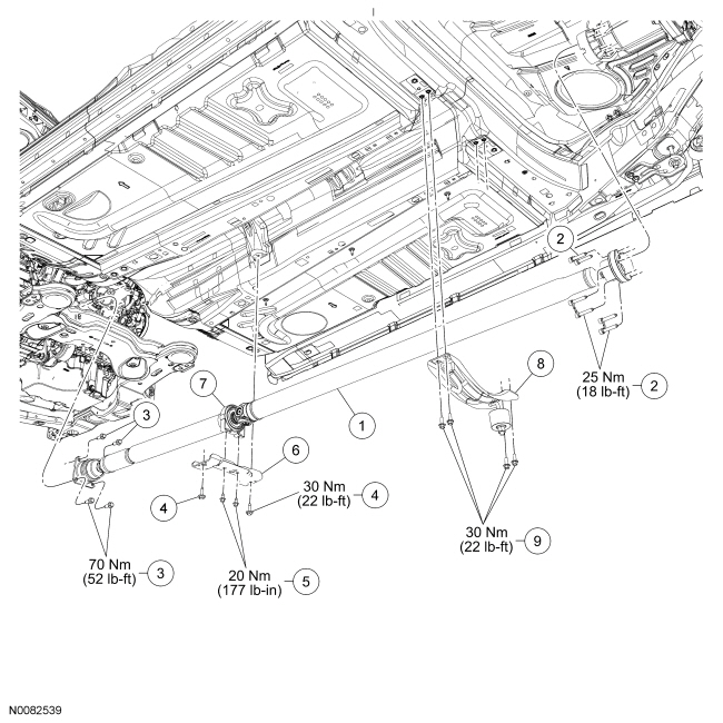
- Remove the 4 exhaust support brace bolts and the exhaust brace.
- To install, tighten to 30 Nm (22 lb-ft).
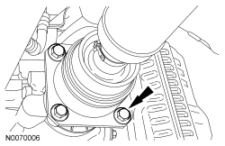
- NOTICE: Do not reuse the bolt and washer assemblies for the
rear Constant Velocity (CV) joint flange. Install new assemblies or damage
to the vehicle may occur.
Remove and discard the 3 Rear Drive Unit (RDU) pinion flange bolt and washer assemblies.
- To install, tighten to 25 Nm (18 lb-ft).
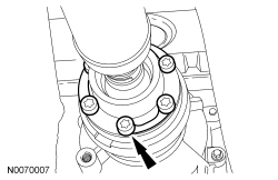
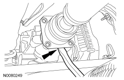
- Separate the driveshaft CV flange from the RDU flange using a flat-blade screwdriver in the area shown.
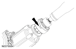
- NOTICE: Do not reuse the Constant Velocity (CV) joint bolts.
Install new bolts or damage to the vehicle may occur.
Remove and discard the 4 Power Transfer Unit (PTU) flange bolts.
- To install, tighten to 70 Nm (52 lb-ft).
- Using a suitable prybar as shown, separate the driveshaft flange from the PTU flange.
- With the help of an assistant, remove the 2 outer center bearing bracket
bolts and the driveshaft.
- To install, tighten to 30 Nm (22 lb-ft).
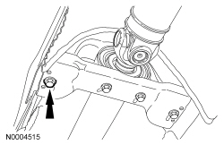
- If necessary, remove the 2 inner center bearing bolts and remove the
bracket.
- To install, tighten to 20 Nm (177 lb-in).
- NOTE: If a driveshaft is installed and driveshaft vibration
is encountered after installation, index the driveshaft. For additional
information, refer to Section 205-00.
To install, reverse the removal procedure.
 Driveline System - General Information
SPECIFICATIONS
Material
General Specifications
DESCRIPTION AND OPERATION
Driveline System
The driveline system consists of the following components:
Center support bearing
Driveshaft assembly
F ...
 Rear Drive Axle/Differential
SPECIFICATIONS
Material
Torque Specifications
DESCRIPTION AND OPERATION
Rear Drive Axle and Differential
The rear drive axle consists of the following components:
Dished circular flange
Full-t ...
Other materials:
Identification Codes
Vehicle Identification Number (VIN)
Vehicle Identification Number (VIN) Locator
The Vehicle Identification Number (VIN) is a 17-digit combination of letters
and numbers. The VIN is stamped on a metal tab riveted to the instrument panel
top, upper left of the dash. The VIN is a ...
Interior Trim and Ornamentation
SPECIFICATIONS
Material
Torque Specifications
DIAGNOSIS AND TESTING
Sunshade
Special Tool(s)
Principles of Operation
Power Sunshade
The power sunshade system consists of the following:
Sunshade switch
Sunshade module
Sunshade motor
Sunshade assembly
Pressing the sunshade switch (a single po ...
Normal scheduled maintenance and log
Intelligent Oil-Life Monitor®
Your vehicle is equipped with an Intelligent Oil-Life Monitor that
determines when the engine oil needs to be changed based on how your
vehicle is used. By using several important factors in its calculations,
the monitor helps reduce the cost of owning your vehicle ...
