Cylinder Head
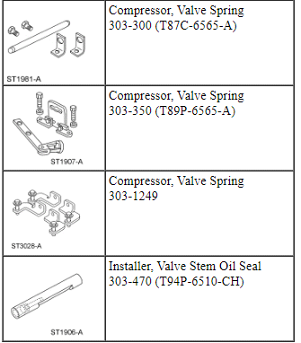
Special Tool(s)
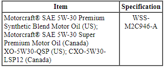
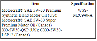
Material
Cylinder Head
NOTE: RH shown, LH similar.
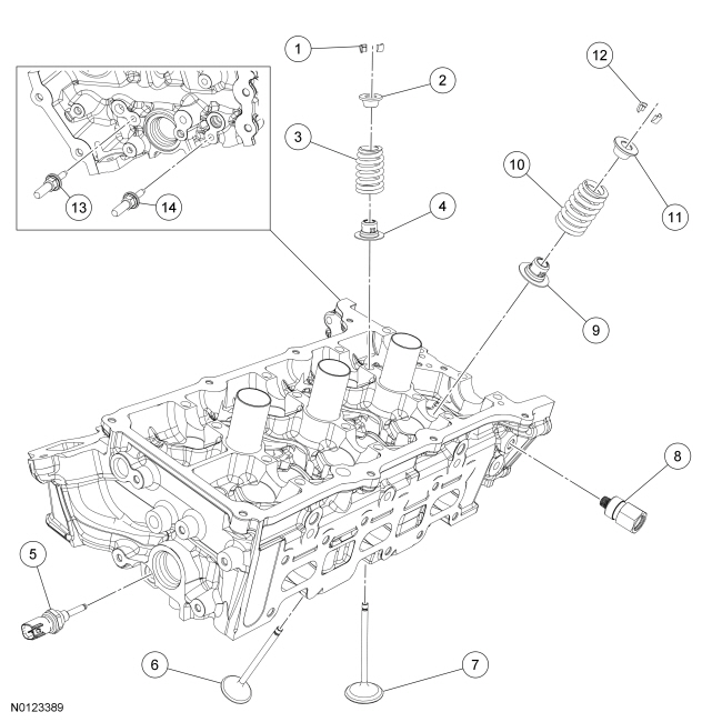
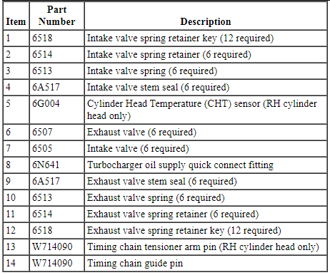
Disassembly
NOTE: If the components are to be reinstalled, they must be installed in the same positions. Mark the components for installation into their original locations.
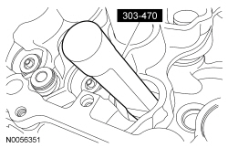
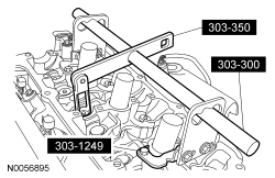
- Using the Valve Spring Compressors, remove the keys, retainer and spring.

- Remove the valve from the cylinder head.
- Remove and discard the valve stem seal.
- Repeat the above steps for each valve.
- Remove the timing chain guide pin and/or timing chain tensioner arm pin.
- Remove the turbocharger oil supply quick connect fitting.
- Inspect and if necessary, replace the quick connect fitting.
- If equipped, remove and discard the Cylinder Head Temperature (CHT) sensor.
Assembly
- NOTE: Lubricate the valve stem seal with clean engine oil prior
to installation.
Using the Valve Stem Oil Seal Installer, install a new valve stem seal.
- Install the valve.
- Using the Valve Spring Compressors, install the valve spring, retainer and key.
- Repeat the above steps for each valve.
- Install the timing chain guide pin and/or timing chain tensioner arm pin
and tighten in 2 stages.
- Stage 1: Tighten to 20 Nm (177 lb-in).
- Stage 2: Tighten an additional 60 degrees.
- Install the turbocharger oil supply quick connect fitting.
- Tighten to 16 Nm (142 lb-in).
- If equipped, install a new CHT sensor.
- Tighten to 10 Nm (89 lb-in).
Piston
Material
Disassembly
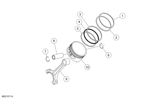
- Remove the piston rings from the piston.
- Discard the piston rings.
- Remove the 2 piston pin retainers and the piston pin.
- Discard the 2 piston pin retainer clips.
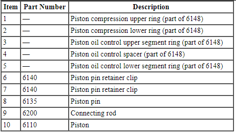
- NOTE: If the piston and/or connecting rod are being installed
new, the piston rod orientation marks and the arrow on the top of the dome
of the piston should be facing toward the front of the engine block.
NOTE: If the piston and connecting rod are to be reinstalled, they must be assembled in the same orientation. Mark the piston orientation to the connecting rod for reassembly.
Separate the piston from the connecting rod.
- Clean and inspect the piston and connecting rod. For additional information, refer to Section 303-00.
Assembly
- Align the piston-to-connecting rod orientation marks and position the connecting rod in the piston.
- Lubricate the piston pin and pin bore with clean engine oil.
- Install the piston pin in the piston and connecting rod assembly.
- Install the new piston pin retaining clips in the piston.
- The piston pin retaining clip gap orientation must be toward the top or dome of piston.
- Lubricate the piston and the new piston rings with clean engine oil.
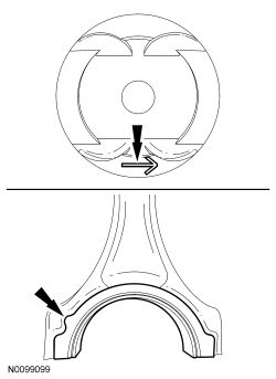
- NOTE: The piston compression upper and lower ring should be
installed with the "O" mark on the ring face pointing up toward the top of
the piston.
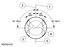
Install the piston rings onto the piston as shown.
- Center line of the piston parallel to the wrist pin bore
- Upper compression ring gap location
- Upper oil control segment ring gap location
- Lower oil control segment ring gap location
- Expander ring and lower compression ring gap location
 Disassembly
Engine
Special Tool(s)
Material
WARNING: Do not smoke, carry lighted tobacco or have an open flame of any
type when working on or near any fuel-related component. Highly flammable
mixtures are a ...
 Assembly
Engine
Special Tool(s)
Material
Engine Upper
Engine Upper - LH Cylinder Head
Engine Upper - RH Cylinder Head
Engine Front
Timing Drive Components
Lower Engine Block (View 1)
Lowe ...
Other materials:
Fuel System - General Information
SPECIFICATIONS
General Specifications
Torque Specifications
DESCRIPTION AND OPERATION
Fuel System
2.0L Gasoline Turbocharged Direct Injection (GTDI)
The fuel system:
is a variable speed Closed Loop Pressure Control (CLPC) Fuel System with
Gasoline Turbocharged Direct Injection (GTDI).
...
Driveshaft
SPECIFICATIONS
Torque Specifications
DESCRIPTION AND OPERATION
Driveshaft
NOTE: All driveshaft assemblies are balanced. If undercoating the
vehicle, protect the driveshaft to prevent overspray of any undercoating
material.
The driveshaft assembly consists of the following:
Rubber-isolat ...
Engine coolant check
Checking the Engine Coolant
The concentration and level of engine coolant should be checked at the
intervals listed in Scheduled Maintenance Information.
Note: Make sure that the level is at the FULL COLD level or within the
COLD FILL RANGE in the coolant reservoir.
Note: Coolant expands wh ...
