SPECIFICATIONS
General Specifications
DESCRIPTION AND OPERATION
Active Park Assist
Component Location
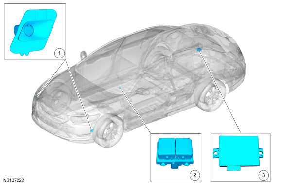
- Active park assist sensor
- Active park assist switch
- Parking aid module
Overview
The active park assist system is a supplementary parking aid that assists the operator in detecting an available parallel parking space and automatically steering the vehicle into the space while the operator controls the accelerator, gearshift and brakes.
The system visually and/or audibly instructs the operator to park the vehicle through messages in the centerstack infotainment display and warning chimes.
System Operation
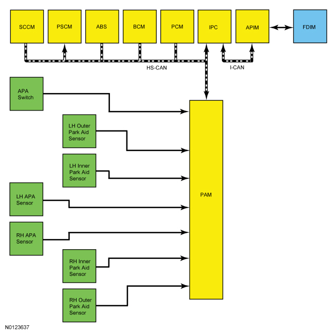
System Diagram
Network Message Chart
Module Network Input Messages - PAM

Module Network Input Messages - PSCM
Module Network Input Messages - IPC
Module Network Input Messages - APIM
Active Park Assist System
NOTE: Refer to the Owner's Literature for additional active park assist messages and graphical centerstack infotainment displays.
The PAM communicates with several modules to control the functions of the active park assist system.
When the active park assist switch is pressed, the message "Searching for parking space on left/right side." is displayed in the centerstack infotainment display. The multifunction switch turn signal input is used to determine the side of vehicle that the driver is searching for a parking space. If the turn signal is not selected, the active park assist system defaults to searching on the passenger side of the vehicle.
The system measures the available parking spaces and their surroundings as the operator drives by to determine if the vehicle can be maneuvered into the available parking space. The minimum parking space length that the active park assist system identifies is approximately 1.3 times the length of the vehicle and is determined by inputs from the active park assist sensors.
Once a suitable parking space is located, the message "Parking space found on left/right side. Pull forward to park." is displayed in the centerstack infotainment display followed by an audible chime from the IPC. The operator pulls the vehicle forward and the message "Parking space found on left/right side. Stop vehicle to park." is displayed in the centerstack infotainment display. Once the operator has stopped the vehicle, the message "Remove hands from steering wheel. Shift to reverse to park on left/right side." is displayed in the centerstack infotainment display. The active park assist system takes control of the steering when the transaxle is placed in REVERSE (R) and no steering wheel operator input torque is detected by the PSCM. The operator has full control of gear-shifting, the accelerator and the brake pedal.
The active park assist system continues to control the steering as the operator moves the vehicle forward. When the front bumper of the vehicle is approximately 304.8 mm (12 in) from the front vehicle, the message "Parking on left/right side. Back up slowly." is displayed in the centerstack infotainment display followed by an audible chime from the IPC. The active park assist system may offer subsequent backward and forward maneuvers (and similar messages) before finalizing the parking sequence.
The PAM determines that the active park maneuvers are completed based on the final vehicle alignment. The vehicle can be located approximately 0 to 304.8 mm (12 in) from the street curb if a curb is detected, otherwise the system aligns the vehicle to the front vehicle. The message "Active Park Assist Finished" is displayed in the centerstack infotainment display followed by an audible chime from the IPC.
Pressing and releasing the active park assist switch at any time disables the active park assist system. If the system is disabled by the operator after the system starts to control the steering, the message "Active Park Assist Cancelled" or "Active Park Assist Deactivated" is displayed in the centerstack infotainment display followed by a warning chime.
The active park assist system utilizes steering angle inputs, vehicle wheel roll count, wheel direction, wheel speed sensor inputs, vehicle speed and transaxle selection to calculate vehicle position and distance in relation to the parking space. The inputs are used by the PAM to command the steering system to assist with the steering wheel control to maneuver the vehicle into the parking space.
The rear parking aid sensors are used to detect a vehicle or object located behind the vehicle in the parking space. The rear parking aid speaker sounds a continuous tone when the rear bumper of the vehicle is approximately 304.8 mm (12 in) from the vehicle to the rear and the message "Stop vehicle. Pull forward slowly." is displayed in the centerstack infotainment display followed by an audible chime from the IPC.
If an input module fault or other system malfunction is present, the active park assist system is disabled or prevents the system from activating. The message "Active Park Assist Fault" is displayed in the centerstack infotainment display and a DTC is set in the PAM.
These conditions can cause the active park assist system to incorrectly align the vehicle in the selected parking space:
- A spare tire or one of the vehicles tires has significantly more or less tread wear than the other tires.
- The factory-installed tire sizes are not used on the vehicle.
- Poor weather conditions such as heavy rain or snow exist.
- The active park assist sensors are damaged or obstructed.
- The curb along the parking space is irregular.
- The vehicle or objects bordering the space are not be positioned correctly. The system aligns the vehicle to the front vehicle when the curb is not detected.
- The parking space length or parked objects position have changed after the vehicle has passed the parking space.
- The temperature around the vehicle changes quickly such as the vehicle driven from a heated garage into the cold or just leaving a car wash before the system was used.
- One of the parked vehicles has a high attachment, such as a salt spreader or moving truck bed, that the sensors cannot detect.
EPAS Control
The EPAS gear assembly is used to control the steering portion of the active park assist system. The gear assembly is comprised of an electrically controlled power rack assembly and a PSCM.
Active Park Assist Message Display
The IPC message center displays the active park assist message.
The following conditions can result in the active park assist system to be cancelled.
Component Description
Active Park Assist Sensors
Long range ultrasonic active park assist sensors continuously send out ultrasonic signals to detect an available parking space and communicate the information back to the PAM. The sensors are active when the vehicle is moving regardless of whether the operator has pressed the active park assist switch. The active park assist sensor distance detection range is approximately 3,911.6 mm (154 in), projecting outward from the side of the vehicle. REFER to Azimuth System Check.
Active Park Assist Switch
A ground signal input to the PAM enables the active park assist system.
DIAGNOSIS AND TESTING
Active Park Assist
DTC Charts
Diagnostics in this manual assume a certain skill level and knowledge of Ford-specific diagnostic practices. Refer to Diagnostic Methods in Section 100-00 for information about these practices.
NOTE: Refer to Description and Operation, Intelligent Access (IA) with Push Button Start in Section 419-01C to review the procedures for achieving the various ignition states (ignition in accessory, ignition on, ignition start, ignition off) on vehicles with this feature.
Symptom Chart
Diagnostics in this manual assume a certain skill level and knowledge of Ford-specific diagnostic practices. Refer to Diagnostic Methods in Section 100-00 for information about these practices.
Pinpoint Tests
Pinpoint Test A: The Active Park Assist Does Not Operate When Switch Is Pressed
Diagnostic Overview
Diagnostics in this manual assume a certain skill level and knowledge of Ford-specific diagnostic practices. Refer to Diagnostic Methods in Section 100-00 for information about these practices.
Refer to Wiring Diagrams Cell 131, Parking Aid for schematic and connector information.
Normal Operation and Fault Conditions
REFER to Active Park Assist Switch in Active Park Assist.
-
Possible Sources
- Wiring, terminals or connectors
- Active park assist switch
- PAM
Visual Inspection and Diagnostic Pre-checks
Before disconnecting the PAM or the sensors, verify that the connectors are properly seated and latched.
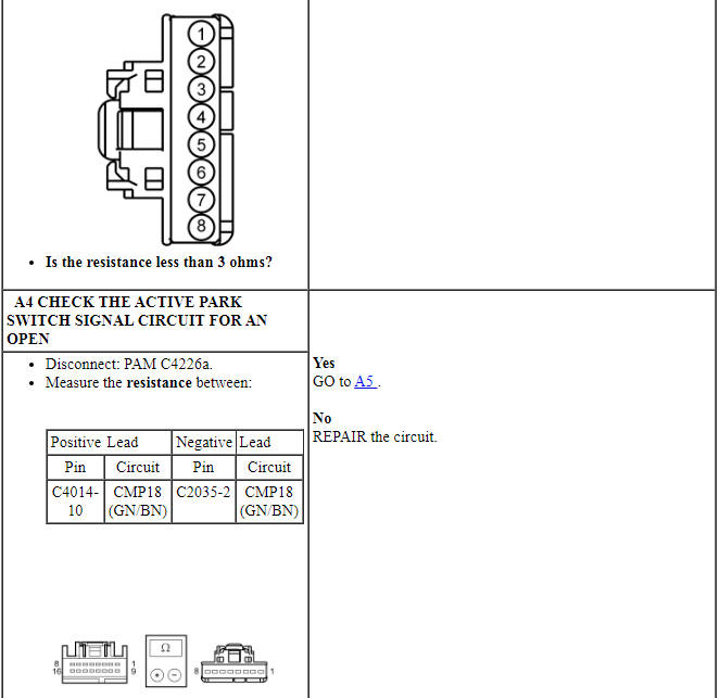
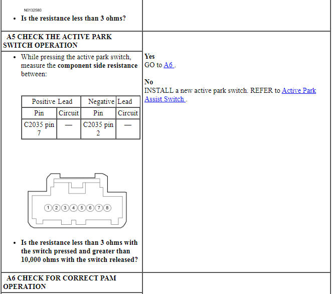
PINPOINT TEST A: THE ACTIVE PARK ASSIST DOES NOT OPERATE WHEN SWITCH IS PRESSED
NOTICE: Use the correct probe adapter(s) when making measurements. Failure to use the correct probe adapter(s) may damage the connector.
Pinpoint Test B: DTC B129C:14 Or DTC B129D:14
Diagnostic Overview
Diagnostics in this manual assume a certain skill level and knowledge of Ford-specific diagnostic practices. Refer to Diagnostic Methods in Section 100-00 for information about these practices.
Refer to Wiring Diagrams Cell 131, Parking Aid for schematic and connector information.
-
Possible Sources
- Wiring, terminals or connectors
- Active park assist sensor(s)
- PAM
Visual Inspection and Diagnostic Pre-checks
Before disconnecting the PAM or the sensors, verify that the connectors are properly seated and latched.
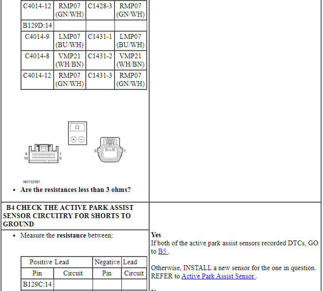
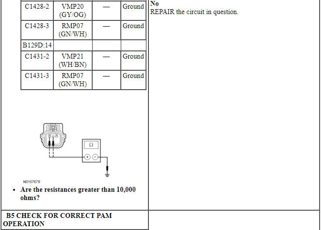
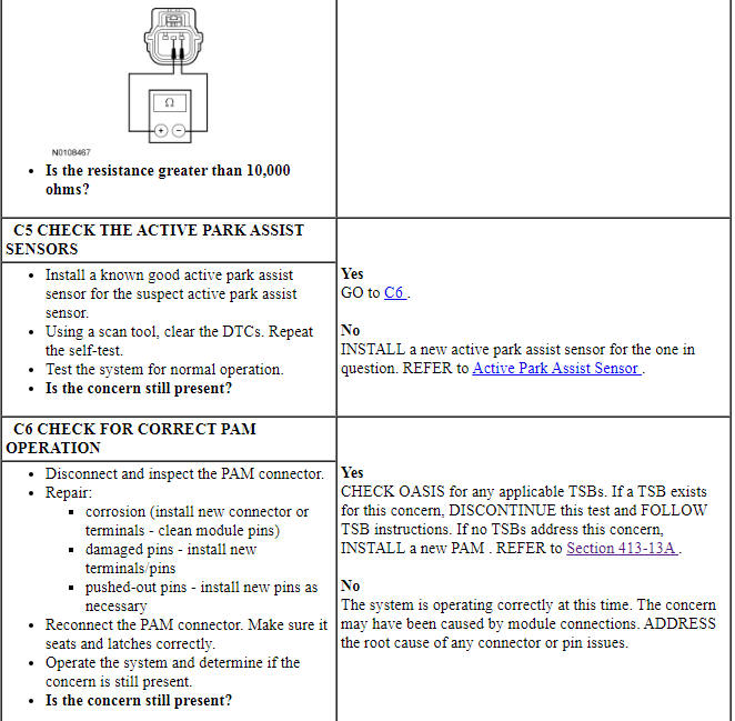
PINPOINT TEST B: DTC B129C:14 OR DTC B129D:14
NOTICE: Use the correct probe adapter(s) when making measurements. Failure to use the correct probe adapter(s) may damage the connector.
Pinpoint Test C: DTC B129C:12 Or DTC B129D:12
Diagnostic Overview
Diagnostics in this manual assume a certain skill level and knowledge of Ford-specific diagnostic practices. Refer to Diagnostic Methods in Section 100-00 for information about these practices.
Refer to Wiring Diagrams Cell 131, Parking Aid for schematic and connector information.
-
Possible Sources
- Wiring, terminals or connectors
- Active park assist sensor(s)
- PAM
Visual Inspection and Diagnostic Pre-checks
Before disconnecting the PAM or the sensors, verify that the connectors are properly seated and latched.
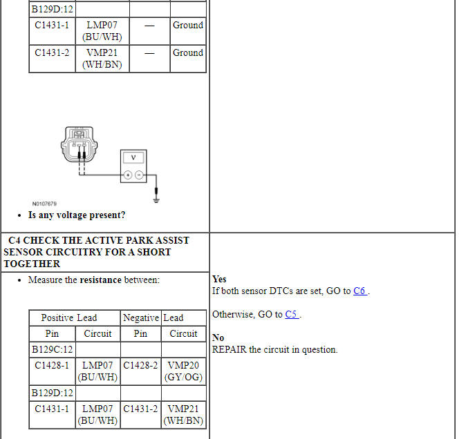
PINPOINT TEST C: DTC B129C:12 OR DTC B129D:12
NOTICE: Use the correct probe adapter(s) when making measurements. Failure to use the correct probe adapter(s) may damage the connector.
Pinpoint Test D: DTC B129C:96 Or DTC B129D:96
Diagnostic Overview
Diagnostics in this manual assume a certain skill level and knowledge of Ford-specific diagnostic practices. Refer to Diagnostic Methods in Section 100-00 for information about these practices.
Refer to Wiring Diagrams Cell 131, Parking Aid for schematic and connector information.
-
Possible Sources
- Active park assist sensor(s)
- PAM
Visual Inspection and Diagnostic Pre-checks
Before disconnecting the PAM or the sensors, verify that the connectors are properly seated and latched.
PINPOINT TEST D: DTC B129C:96 OR DTC B129D:96
Pinpoint Test E: DTC B1303:11
Diagnostic Overview
Diagnostics in this manual assume a certain skill level and knowledge of Ford-specific diagnostic practices. Refer to Diagnostic Methods in Section 100-00 for information about these practices.
Refer to Wiring Diagrams Cell 131, Parking Aid for schematic and connector information.
-
Possible Sources
- Wiring, terminals or connectors
- Active park assist switch
- PAM
Visual Inspection and Diagnostic Pre-checks
Before disconnecting the PAM or the sensors, verify that the connectors are properly seated and latched.
PINPOINT TEST E: DTC B1303:11
NOTICE: Use the correct probe adapter(s) when making measurements. Failure to use the correct probe adapter(s) may damage the connector.
Pinpoint Test F: DTC B1304:68
Diagnostic Overview
Diagnostics in this manual assume a certain skill level and knowledge of Ford-specific diagnostic practices. Refer to Diagnostic Methods in Section 100-00 for information about these practices.
Refer to Wiring Diagrams Cell 131, Parking Aid for schematic and connector information.
Normal Operation and Fault Conditions
REFER to Active Park Assist System in Active Park Assist.
This fault occurred while the operator was using the active park assist system and the system had control of the steering. During the failure, the operator should see the centerstack infotainment display message "Active Park Assist Fault" followed by an audible chime.
-
Possible Sources
- PSCM
- PAM
Visual Inspection and Diagnostic Pre-checks
Before disconnecting the PAM or the sensors, verify that the connectors are properly seated and latched.
PINPOINT TEST F: B1304:68
NOTICE: Use the correct probe adapter(s) when making measurements. Failure to use the correct probe adapter(s) may damage the connector.
Pinpoint Test G: "Active Park Assist Fault" Message Is Displayed In The Centerstack Infotainment Display
Diagnostic Overview
Diagnostics in this manual assume a certain skill level and knowledge of Ford-specific diagnostic practices. Refer to Diagnostic Methods in Section 100-00 for information about these practices.
Refer to Wiring Diagrams Cell 131, Parking Aid for schematic and connector information.
Normal Operation and Fault Conditions
Refer to Active Park Assist System in Active Park Assist.
-
Possible Sources
- Wiring, terminals or connectors
- Active park assist switch
- Active park assist sensor(s)
- PSCM
- IPC
- SCCM
- PCM
- ABS module
- PAM
Visual Inspection and Diagnostic Pre-checks
Before disconnecting the PAM or the sensors, verify that the connectors are properly seated and latched.
PINPOINT TEST G: "ACTIVE PARK ASSIST FAULT" MESSAGE IS DISPLAYED IN THE CENTERSTACK INFOTAINMENT DISPLAY
Pinpoint Test H: DTC U0100:00
Diagnostic Overview
Diagnostics in this manual assume a certain skill level and knowledge of Ford-specific diagnostic practices. Refer to Diagnostic Methods in Section 100-00 for information about these practices.
Refer to Wiring Diagrams Cell 131, Parking Aid for schematic and connector information.
-
Possible Sources
- PCM
- PAM
Visual Inspection and Diagnostic Pre-checks
Before disconnecting the PAM or the sensors, verify that the connectors are properly seated and latched.
PINPOINT TEST H: DTC U0100:00

Pinpoint Test I: DTC U0121:00
Diagnostic Overview
Diagnostics in this manual assume a certain skill level and knowledge of Ford-specific diagnostic practices. Refer to Diagnostic Methods in Section 100-00 for information about these practices.
-
Possible Sources
- ABS module
- PAM
Visual Inspection and Diagnostic Pre-checks
Before disconnecting the PAM or the sensors, verify that the connectors are properly seated and latched.
PINPOINT TEST I: DTC U0121:00
Pinpoint Test J: DTC U0131:00
Diagnostic Overview
Diagnostics in this manual assume a certain skill level and knowledge of Ford-specific diagnostic practices. Refer to Diagnostic Methods in Section 100-00 for information about these practices.
-
Possible Sources
- PSCM
- PAM
Visual Inspection and Diagnostic Pre-checks
Before disconnecting the PAM or the sensors, verify that the connectors are properly seated and latched.
PINPOINT TEST J: DTC U0131:00
Pinpoint Test K: DTC U0155:00
Diagnostic Overview
Diagnostics in this manual assume a certain skill level and knowledge of Ford-specific diagnostic practices. Refer to Diagnostic Methods in Section 100-00 for information about these practices.
Refer to Wiring Diagrams Cell 131, Parking Aid for schematic and connector information.
-
Possible Sources
- IPC
- PAM
Visual Inspection and Diagnostic Pre-checks
Before disconnecting the PAM or the sensors, verify that the connectors are properly seated and latched.
PINPOINT TEST K: DTC U0155:00
Pinpoint Test L: DTC U0212:00
Diagnostic Overview
Diagnostics in this manual assume a certain skill level and knowledge of Ford-specific diagnostic practices. Refer to Diagnostic Methods in Section 100-00 for information about these practices.
Refer to Wiring Diagrams Cell 131, Parking Aid for schematic and connector information.
-
Possible Sources
- SCCM
- PAM
Visual Inspection and Diagnostic Pre-checks
Before disconnecting the PAM or the sensors, verify that the connectors are properly seated and latched.
PINPOINT TEST L: DTC U0212:00

Pinpoint Test M: DTC U0140:00
Diagnostic Overview
Diagnostics in this manual assume a certain skill level and knowledge of Ford-specific diagnostic practices. Refer to Diagnostic Methods in Section 100-00 for information about these practices.
Refer to Wiring Diagrams Cell 131, Parking Aid for schematic and connector information.
-
Possible Sources
- BCM
- PAM
Visual Inspection and Diagnostic Pre-checks
Before disconnecting the PAM or the sensors, verify that the connectors are properly seated and latched.
PINPOINT TEST M: DTC U0140:00

GENERAL PROCEDURES
Azimuth System Check
Minimum Detectable Object Locations
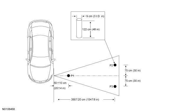
- NOTE: The object used in this system check can be fabricated
using a 9 cm diameter (3 in I.D.) pipe, 122 cm (48 in) in length (available
as Polyvinyl Chloride (PVC) pipe, or similar from a hardware or plumbing
supply).
NOTE: The following system check should be carried out with the vehicle on a level surface.
NOTE: The procedure must be carry out within 30 seconds per each location. If the time has been exceeded, the ignition must be turned to the OFF position and the procedure needs to be started again.
Turn the ignition to ON, engine off.
- Apply the parking brake.
- Place the gearshift in DRIVE (D).
- Verify that the Parking Aid Module (PAM) detects the object above when placed in the 3 specified locations (P1, P2, and P3) and record the distances.
- Confirm that the recorded distances are with in the specification
ranges.
- If the PAM does not detect the object above within the specified ranges, refer to Active Park Assist in the Diagnosis and Testing portion of this section.
REMOVAL AND INSTALLATION
Active Park Assist Sensor
NOTE: Left side shown, right side similar.
Removal and Installation
- Remove the front lower air deflector.
- Disconnect the electrical connector.
- With a suitable tool (such as a flat-blade screwdriver), gently pry the
retaining tabs to remove the active park assist sensor(s).
- Remove the active park assist sensor(s) from the front bumper cover.
- To install, reverse the removal procedure.
- After installing the sensor(s), use the scan tool to verify that the active park assist sensor PIDs responding correctly. Carry out the Azimuth System Check. If the parking aid sensor does not respond correctly, refer to Active Park Assist in the Diagnosis and Testing.
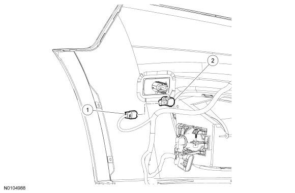
Active Park Assist Switch
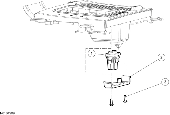
Removal and Installation
- Remove the selector level trim panel. For additional information, refer to Console - Floor in Section 501-12.
- Disconnect the electrical connector.
- Remove the 2 screws.
- Remove the active park assist bracket and switch from the selector level trim panel.
- To install, reverse the removal procedure.
 Parking Aid - Visual
SPECIFICATIONS
General Specifications
DESCRIPTION AND OPERATION
Parking Aid
Component Location
Overview
The video camera system visually aids the driver while reversing or reverse
parking the vehi ...

Other materials:
Blind Spot Information System (BLIS) with Cross Traffic Alert (CTA)
WARNING: To help avoid injuries, NEVER use the BLIS® as a
replacement for using the interior and exterior mirrors and
looking over your shoulder before changing lanes. BLIS® is not a
replacement for careful driving and only an assist.
BLIS® aids the driver in detecting
vehicles that may ha ...
Specifications, Description and Operation
SPECIFICATIONS
Material
Torque Specifications
DESCRIPTION AND OPERATION
Glass, Frames and Mechanisms
Overview
The accessory delay relay, located in the BCM, provides voltage for the
operation of the power windows and the roof opening panel (if equipped). Refer
to Delayed Accessory Power.
St ...
General Procedures, Removal and Installation
GENERAL PROCEDURES
Belt-Minder Deactivating/Activating
NOTE: If you are using MyKey, the Belt-Minder cannot be disabled. If
the Belt-Minder has been previously disabled, it is re-enabled during the use
of MyKey.
Apply the parking brake before deactivating/activating the Belt-Minder.
Plac ...
