Safety Belt Anchor and Pretensioner
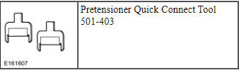
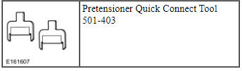
Special Tool(s)
Removal and Installation
WARNING: All safety belt components must be inspected and corrected as part of any collision repair. Inspect all safety belt components as prescribed by Safety Belt Inspection and Repair After a Collision found in Section 501-20A General Procedures of this manual. Failure to follow this instruction may result in incorrect operation of the safety belt system and increase the risk of serious personal injury or death in a crash.
WARNING: Never disassemble or tamper with seat belt deployable components, including pretensioners, load limiters and inflators. Never back probe deployable device electrical connectors. Tampering or back probing may cause an accidental deployment and result in personal injury or death.
NOTE: Removal steps in this procedure may contain installation details.
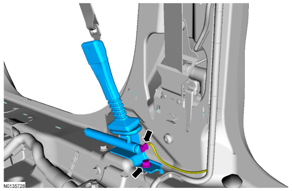
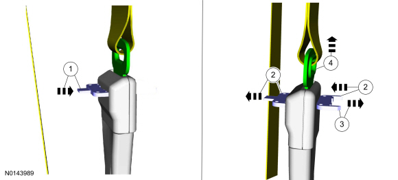
- Depower the SRS. Refer to Section 501-20B.
-
- Special Tool(s): Pretensioner Quick Connect Tool 501-403.
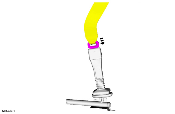
- NOTE: Allow insertion of the second tool to push the first
tool from the mini-buckle.
Special Tool(s): Pretensioner Quick Connect Tool 501-403.
- -
- -

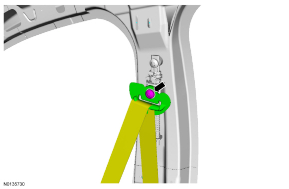
- Remove the lower B-pillar trim panel. Refer to Section 501-05.
-
- To install, tighten to 48 Nm (35 lb-ft).
- NOTE: During installation, make sure the safety belt webbing is
not twisted and the safety belts and buckles are accessible to the
occupants.
To install, reverse the removal procedure.
- NOTE: During the latching sequence, tongue insertion should not be hindered by excessive effort and a click will be heard when the safety belt buckle latches the tongue. If the safety belt tongue cannot be inserted into the safety belt anchor and pretensioner, it will be necessary to reset the latch inside the safety belt anchor and pretensioner using the service tools.
- Repower the SRS. Refer to Section 501-20B.
- Check the active restraint system for correct operation. Refer to the appropriate Functional Test in Safety Belt System.
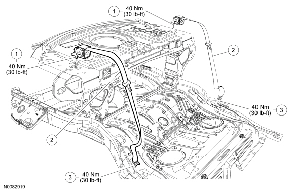
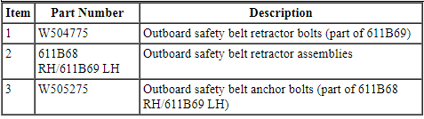
Safety Belt Retractor and Pretensioner
Special Tool(s)
Removal and Installation
WARNING: All safety belt components must be inspected and corrected as part of any collision repair. Inspect all safety belt components as prescribed by Safety Belt Inspection and Repair After a Collision found in Section 501-20A General Procedures of this manual. Failure to follow this instruction may result in incorrect operation of the safety belt system and increase the risk of serious personal injury or death in a crash.
WARNING: Never disassemble or tamper with seat belt deployable components, including pretensioners, load limiters and inflators. Never back probe deployable device electrical connectors. Tampering or back probing may cause an accidental deployment and result in personal injury or death.
NOTE: Removal steps in this procedure may contain installation details.
- Depower the SRS. Refer to Section 501-20B.
-
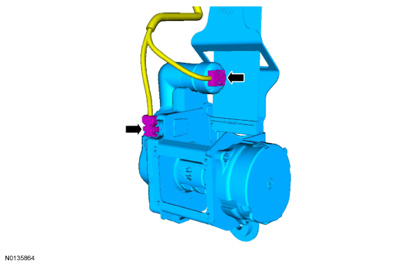
- Special Tool(s): Pretensioner Quick Connect Tool 501-403.
- NOTE: Allow insertion of the second tool to push the first
tool from the mini-buckle.
Special Tool(s): Pretensioner Quick Connect Tool 501-403.
- -
- -
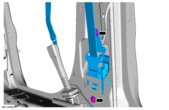
- Remove the B-pillar trim panels. Refer to Section 501-05.
-
- To install, tighten to 40 Nm (30 lb-ft).
- NOTE: RH shown, LH similar.
- To install, tighten to 40 Nm (30 lb-ft).
- RH side.
- LH side.
- NOTE: During installation, make sure the safety belt webbing is
not twisted and the safety belts and buckles are accessible to the
occupants.
To install, reverse the removal procedure.
- NOTE: During the latching sequence, tongue insertion should not be hindered by excessive effort and a click will be heard when the safety belt buckle latches the tongue. If the safety belt tongue cannot be inserted into the safety belt anchor and pretensioner, it will be necessary to reset the latch inside the safety belt anchor and pretensioner using the service tools.

- Repower the SRS. Refer to Section 501-20B.
- Check the active restraint system for correct operation. Refer to the appropriate Functional Test in Safety Belt System.
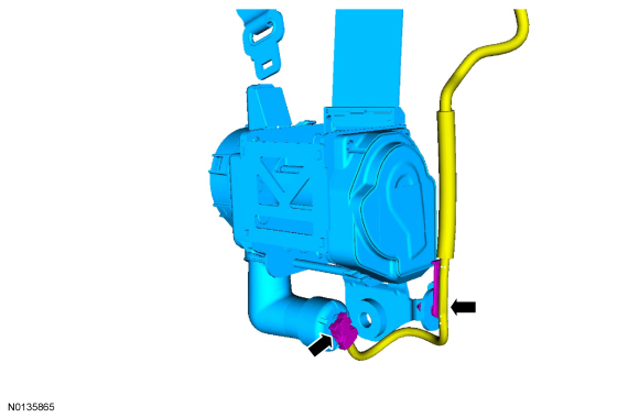
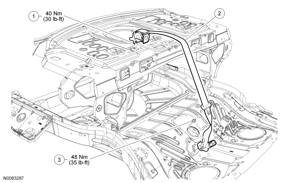
Safety Belt Retractor - Rear, Center
Removal and Installation
WARNING: All safety belt components must be inspected and corrected as part of any collision repair. Inspect all safety belt components as prescribed by Safety Belt Inspection and Repair After a Collision found in Section 501-20A General Procedures of this manual. Failure to follow this instruction may result in incorrect operation of the safety belt system and increase the risk of serious personal injury or death in a crash.
- Remove the rear seat cushion. For additional information, refer to Section 501-10.
- Remove the parcel shelf. For additional information, refer to Section 501-05.
- Remove the safety belt retractor anchor nut.
- To install, tighten to 48 Nm (35 lb-ft).
- Remove the bolt and safety belt retractor.
- To install, tighten to 40 Nm (30 lb-ft).
- NOTE: Before installation, make sure the safety belt webbing is
not twisted and the safety belts and buckles are accessible to the
occupants.
To install, reverse the removal procedure.
- Check the active restraint system for correct operation. For additional information, refer to the appropriate Functional Test procedure in Safety Belt System in this section.
Safety Belt Retractor - Rear, Outboard
NOTE: Base vehicle shown.
Removal and Installation
WARNING: All safety belt components must be inspected and corrected as part of any collision repair. Inspect all safety belt components as prescribed by Safety Belt Inspection and Repair After a Collision found in Section 501-20A General Procedures of this manual. Failure to follow this instruction may result in incorrect operation of the safety belt system and increase the risk of serious personal injury or death in a crash.
NOTE: Removal steps in this procedure may contain installation details.
- Remove the parcel shelf. Refer to Section 501-05.
- NOTE: Police vehicle shown.
To install, tighten to 40 Nm (30 lb-ft).
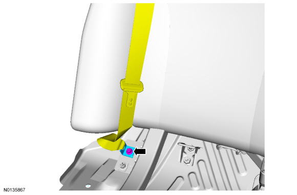
- Remove the bolt and safety belt retractor.
- To install, tighten to 40 Nm (30 lb-ft).
- NOTE: During installation, make sure the safety belt webbing is
not twisted and the safety belts and buckles are accessible to the
occupants.
To install, reverse the removal procedure.
- Check the active restraint system for correct operation. Refer to the appropriate Functional Test in Safety Belt System.
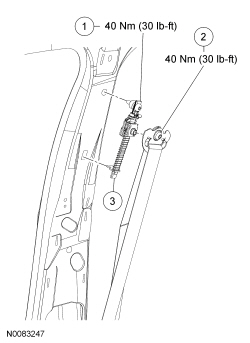
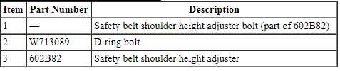
Safety Belt Shoulder Height Adjuster
NOTE: LH shown, RH similar.
Removal and Installation
WARNING: All safety belt components must be inspected and corrected as part of any collision repair. Inspect all safety belt components as prescribed by Safety Belt Inspection and Repair After a Collision found in Section 501-20A General Procedures of this manual. Failure to follow this instruction may result in incorrect operation of the safety belt system and increase the risk of serious personal injury or death in a crash.
- Remove the upper B-pillar trim panel. For additional information, refer to Section 501-05.
- Remove the bolt and position the D-ring aside.
- To install, tighten to 40 Nm (30 lb-ft).
- Remove the safety belt shoulder height adjuster.
- Remove the bolt.
To install, tighten to 40 Nm (30 lb-ft).
- Rotate the safety belt shoulder height adjuster and unhook it from the B-pillar.
- Remove the bolt.
- NOTE: Before installation, make sure the safety belt webbing is
not twisted and the safety belts and buckles are accessible to the
occupants.
To install, reverse the removal procedure.
- Check the active restraint system for correct operation. For additional information, refer to the appropriate Functional Test procedure in Safety Belt System in this section.
Safety Belt Buckle - Front
Removal and Installation
WARNING: All safety belt components must be inspected and corrected as part of any collision repair. Inspect all safety belt components as prescribed by Safety Belt Inspection and Repair After a Collision found in Section 501-20A General Procedures of this manual. Failure to follow this instruction may result in incorrect operation of the safety belt system and increase the risk of serious personal injury or death in a crash.
WARNING: Never disassemble or tamper with seat belt deployable components, including pretensioners, load limiters and inflators. Never back probe deployable device electrical connectors. Tampering or back probing may cause an accidental deployment and result in personal injury or death.
NOTE: Removal steps in this procedure may contain installation details.
- Remove the front seat. Refer to Section 501-10.
-
- -
- -
- To install, tighten to 48 Nm (35 lb-ft).
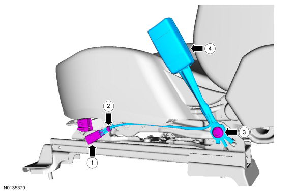
- To install, reverse the removal procedure.
- Install the front seat. Refer to Section 501-10.
- Check the active restraint system for correct operation. Refer to the appropriate Functional Test in Safety Belt System.
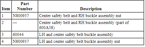
Safety Belt Buckle - Rear
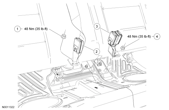
Removal and Installation
WARNING: All safety belt components must be inspected and corrected as part of any collision repair. Inspect all safety belt components as prescribed by Safety Belt Inspection and Repair After a Collision found in Section 501-20A General Procedures of this manual. Failure to follow this instruction may result in incorrect operation of the safety belt system and increase the risk of serious personal injury or death in a crash.
NOTE: The RH safety belt buckle is a part of the center safety belt retractor assembly and is not serviced separately. To remove the RH safety belt buckle, refer to Safety Belt Retractor - Rear, Center in this section.
- Remove the rear seat cushion. For additional information, refer to Section 501-10.
- Remove the nut and LH center safety belt buckle assembly.
- To install, tighten to 48 Nm (35 lb-ft).
- NOTE: Before installation, make sure the safety belt webbing is
not twisted and the safety belts and buckles are accessible to the
occupants.
To install, reverse the removal procedure.
- Check the active restraint system for correct operation. For additional information, refer to the appropriate Functional Test procedure in Safety Belt System in this section.
Child Safety Seat Tether Anchor - LATCH
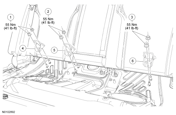
- RH lower anchors and tethers for children nuts
- Center lower anchors and tethers for children nuts
- LH lower anchors and tethers for children nuts
- RH lower anchors and tethers for children
- Center lower anchors and tethers for children
- LH lower anchors and tethers for children
Removal and Installation
WARNING: All safety belt components must be inspected and corrected as part of any collision repair. Inspect all safety belt components as prescribed by Safety Belt Inspection and Repair After a Collision found in Section 501-20A General Procedures of this manual. Failure to follow this instruction may result in incorrect operation of the safety belt system and increase the risk of serious personal injury or death in a crash.
- Remove the rear seat cushion. For additional information, refer to Section 501-10.
- Remove the 2 nuts and the affected lower anchors and tethers for
children.
- To install, tighten to 55 Nm (41 lb-ft).
- To install, reverse the removal procedure.
 General Procedures
Safety Belt Cleaning
WARNING:
Do not bleach or re-dye the safety belt webbing, as the webbing may weaken.
Failure to follow this instruction may increase the risk of serious personal
inj ...

Other materials:
Diagnosis and Testing
Automatic Transmission
Special Tool(s)
Material
DTC Chart
Diagnostics in this manual assume a certain skill level and knowledge of
Ford-specific diagnostic practices. Refer to Diagnostic Methods in Section
100-00 for information about these practices.
For all other DTCs, refe ...
Interior luggage compartment release
WARNING: Keep vehicle doors and luggage compartment locked
and keep keys and remote transmitters out of a child’s reach.
Unsupervised children could lock themselves in the trunk and risk
injury. Children should be taught not to play in vehicles.
WARNING: Do not leave children, unreliable adu ...
In-Vehicle Repair
Upper Intake Manifold
Removal
NOTICE: If the engine is repaired or replaced because of upper
engine failure, typically including valve or piston damage, check the intake
manifold for metal debris. If metal debris is found, install a new intake
manifold. Failure to follow these instructions c ...
