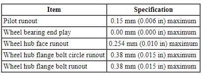
SPECIFICATIONS
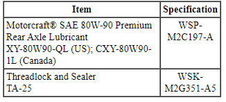
Material
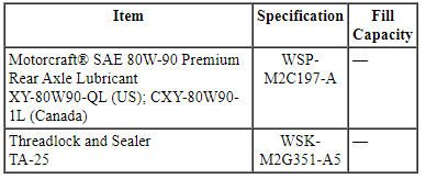
General Specifications
DESCRIPTION AND OPERATION
Driveline System
The driveline system consists of the following components:
- Center support bearing
- Driveshaft assembly
- Front halfshafts
- Rear halfshafts
- Active Torque Coupling (ATC)/rear axle
On Front Wheel Drive (FWD) vehicles, the transaxle transmits power from the engine to the halfshafts.
On All-Wheel Drive (AWD) vehicles, power is transmitted from the engine through the transaxle to the Power Transfer Unit (PTU). The PTU transfers engine power from the transaxle to the front halfshafts, and through the driveshaft to the ATC /rear axle and halfshafts. For information on the PTU, refer to Section 308-07B.
The engine angle is built into the engine mounts. If the engine angle is out of specification, the engine mounts must be inspected for damage. Refer to the appropriate section in Group 303 for the procedure.
Vehicle Certification (VC) Label Example
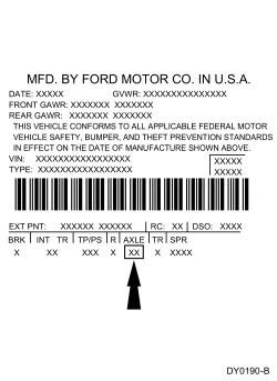
The Vehicle Certification (VC) label is located in the driver door jamb. The axle code is on the VC label. Refer to Section 100-01.
The axle ratio is 2.93 and the ring gear has a diameter of 174 mm (6.85 in).
The wheel speed sensor rings for FWD vehicles are located on the front halfshafts and are mounted to the rear inner spindles.
The wheel speed sensor rings are located on the front and rear halfshafts for AWD vehicles.
Driveshaft
The driveshaft is a 2-piece shaft with a rubber isolated center bearing.
The driveshaft is a balanced assembly and has traditional balance weights attached (spot-welded) by the manufacturer.
U-joints
The CV and U-joints are installed new with the driveshaft.
The front and rear CV joints are:
- lubricated with a special lubricant and require no additional lubrication.
The center U-joints are:
- a lubed-for-life design that requires no periodic lubrication.
- equipped with nylon thrust washers located at the base of each bearing cup which control end play, position the needle bearings and improve grease movement.
Rear Drive Unit (RDU)
The ATC /Rear Drive Unit (RDU) is serviced as an assembly.
Each halfshaft is held in the RDU case by a driveshaft bearing retainer circlip that is located on the inner CV joint stub shaft pilot bearing housing. When each halfshaft is installed, the driveshaft bearing retainer circlip engages a slot in the RDU side gear.
The RDU operates as follows:
- The RDU pinion receives power from the engine through the transaxle, PTU, driveshaft and ATC, and is always engaged.
- The pinion gear rotates the ring gear, which is bolted to the differential case outer flange.
- Inside the differential case, 2 differential pinion gears are mounted on a differential pinion shaft that is pinned to the differential case.
- These differential pinion gears are engaged with the differential side gears, to which the halfshafts are splined.
- As the differential case turns, it rotates the halfshafts and rear wheels.
- When it is necessary for one wheel and halfshaft to rotate faster than the other, the faster turning differential side gear causes the differential pinion gears to roll on the slower turning differential side gear. This allows differential action between the 2 halfshafts.
Halfshafts
NOTICE: An inspection of the outer and inner Constant Velocity (CV) joint boots is necessary so that if damage or grease leakage is evident, installation of a new halfshaft can take place immediately. Continued operation with damage or grease leakage will result in CV joint wear and noise due to contamination and loss of the CV joint grease.
The drive halfshafts consist of the following components:
- Inner CV joints
- Outer CV joints
- CV joint boot clamps
- CV joint boots
- Tripod joint housings
- Retainer circlips
- Front intermediate shaft bearing
The front intermediate shaft bearing is pressed on and is only serviced as an assembly with the intermediate shaft.
- The inner and outer CV joints connect to a splined shaft. A circlip holds the cross groove inner race assembly (inner CV joint) together.
- A circlip retains the splined inner CV joint. Install a new axle circlip each time the halfshaft is removed from the vehicle.
- A wheel hub nut secures the side shaft assembly (interconnecting shaft and outer CV joint) to the wheel hub. Install a new wheel hub nut each time the halfshaft is removed from the vehicle.
Halfshaft Handling
NOTICE: Handle the halfshaft only by the interconnecting shaft to avoid pull-apart and potential damage to the Constant Velocity (CV) joints. Damage will occur to an assembled inner CV joint if it is over-plunged outward from the joint housing or over angled.
NOTICE: When disconnecting the lower ball joint, do not allow the stud to impact the halfshaft as this may damage the Constant Velocity (CV) joint boot seal.
Handle all halfshaft components carefully during removal and installation procedures. Never use a hammer to remove or install the halfshafts. Never use the halfshaft assembly as a lever to position other components. Always support the free-end of the halfshaft. Do not allow the boots to contact sharp edges or hot exhaust components. Do not drop assembled halfshafts. The impact may cut the boots from the inside without evidence of external damage. When disconnecting the lower ball joint, do not allow the stud to impact the halfshaft as this may damage the CV joint bolt seal.
DIAGNOSIS AND TESTING
Driveline System
Material
Principals of Operation
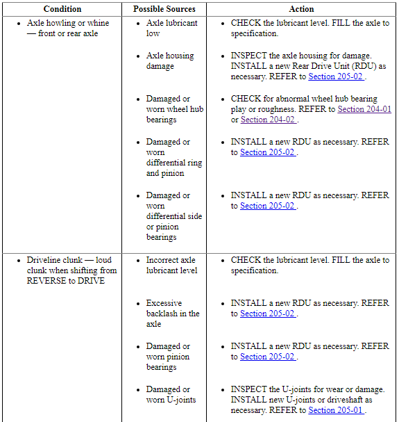
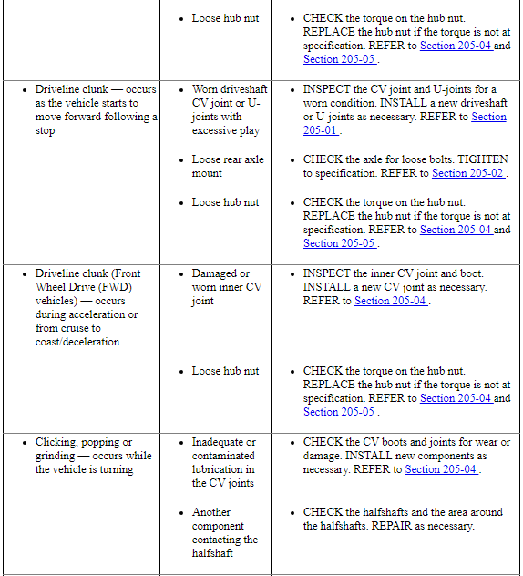
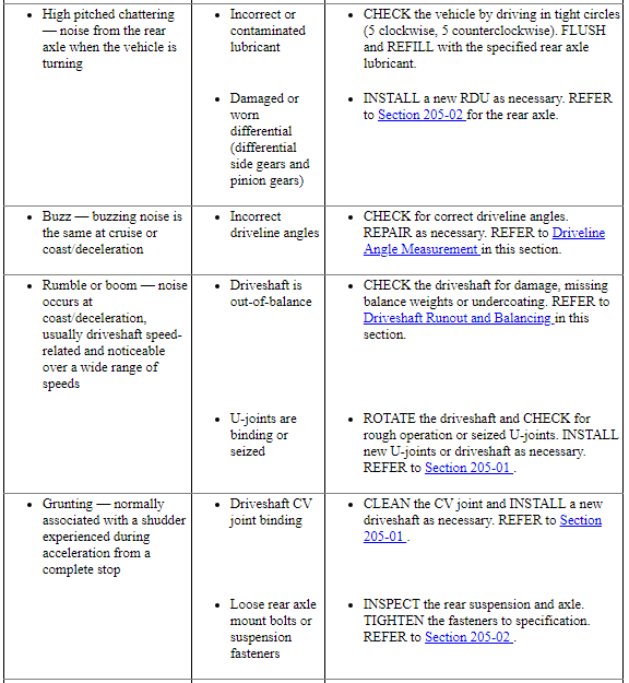
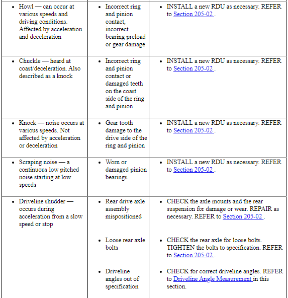
Driveline System - General Information
The driveline system enables the power generated by the engine and transferred through the transmission in Front Wheel Drive (FWD), or the transmission and the Power Transfer Unit (PTU) in All-Wheel Drive (AWD) to place the vehicle in motion. Rotational torque received from the transmission or PTU is delivered to the front wheels by halfshafts or the rear axle by way of the driveshaft(s). The U-joints or CV joints at the ends of the shafts allow the shafts to rotate smoothly in an allowable angle plane. The rotational torque is introduced into the axle drive pinion which drives the differential ring gear. The ring gear is bolted to the axle differential which divides the torque between the left and right axle shafts, while permitting the shafts to turn at different speeds when required, such as when cornering.
Inspection and Verification
- Verify the customer concern.
- Visually inspect for obvious signs of mechanical damage.
Visual Inspection Chart
Mechanical
- U-joints
- CV joints and boots
- Center bearings
- Driveshaft tubes
- Mounting brackets
- Flanges
- Housing and cover damage
- If an obvious cause for an observed or reported concern is found, correct the cause (if possible) before proceeding to the next step.
- If the cause is not visually evident, verify the symptom and GO to Symptom Chart - NVH.
Driveshaft Center U-Joint and CV Joint Inspection
With the vehicle in NEUTRAL, position it on a hoist. Refer to Section 100-02. Rotate the driveshaft by hand. Check for rough operation or seizure of the U-joints or CV joints. Install a new driveshaft if it shows signs of seizure, excessive wear or incorrect seating. Refer to Section 205-01.
Driveshaft Center Bearing
With the vehicle in NEUTRAL, position it on a hoist. Refer to Section 100-02. Rotate the driveshaft by hand. If the bearings show signs of roughness or are noisy, install a new driveshaft assembly. Refer to Section 205-01.
Symptom Chart - NVH
NOTE: NVH symptoms should be identified using the diagnostic tools that are available. For a list of these tools, an explanation of their uses and a glossary of common terms, refer to Section 100-04. Since it is possible any one of multiple systems may be the cause of a symptom, it may be necessary to use a process of elimination type of diagnostic approach to pinpoint the responsible system. If this is not the causal system for the symptom, refer back to Section 100-04 for the next likely system and continue diagnosis.
Analysis of Leakage
Clean up the leaking area enough to identify the exact source.
A plugged Rear Drive Unit (RDU) housing vent can cause excessive pinion seal lip wear due to internal pressure buildup.
Verify the RDU lubricant level is even with the bottom of the fill hole.
Axle Vent
A plugged vent will cause excessive seal lip wear due to internal pressure buildup. If a leak occurs, check the vent. If the vent cannot be cleared, install a new vent.
Drive Pinion Seal
Leaks at the drive pinion seal originate from the following causes:
- Damaged seal
- Worn seal journal surface
Any damage to the seal bore (dings, dents, gouges or other imperfections) distorts the seal casing and allows leakage past the outer edge of the drive pinion seal.
The drive pinion seal can be torn, cut or gouged if it is not installed correctly. The spring that holds the drive pinion seal against the pinion flange may be knocked out and allow fluid to pass the lip.
Metal chips trapped at the sealing lip can cause oil leaks. These can cause a wear groove on the drive pinion flange and result in pinion seal wear.
When a seal leak occurs on vehicles equipped with a stamped steel cover, install a new drive pinion seal and check the vent to make sure it is clean and free of foreign material.
On some vehicles a new drive pinion flange must be installed if any of these conditions exist.
Drive Pinion Nut
NOTICE: Install the drive pinion nut to the correct torque specifications or damage to the differential components may occur.
On some high-mileage vehicles, oil may leak through the threads of the drive pinion nut. On some vehicles this condition can be corrected by installing a new drive pinion nut and applying threadlock and sealer on the threads and nut face.
Differential Seals
NOTICE: When installing shafts, do not allow splines to contact seals during installation or damage to the seals may occur.
Halfshaft pilot bearing housing seals are susceptible to the same types of damage as drive pinion seals if incorrectly installed. The seal bore must be clean and the lip handled carefully to avoid cutting or tearing it. The seal journal surface must be free of nicks, gouges and rough surface texture.
For information on differential seals, refer to Section 205-02.
GENERAL PROCEDURES
Driveline Angle Measurement
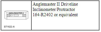
Special Tool(s)
NOTE: This procedure does not apply to CV joints, flex couplers or double cardan joints that are used in some driveshafts. This check is for single-cross and roller-style joints found in the driveshafts.
NOTE: Prior to checking driveline angularity, inspect the U-joints for correct operation.
NOTE: An incorrect driveline angle can cause a vibration or shudder. For additional information, refer to Section 100-04.
NOTE: Driveline angularity is the angular relationship between the engine crankshaft, the driveshaft and the rear axle pinion. Factors determining driveline angularity include ride height, rear spring and engine mounts.
All vehicles
- Carry out the following preliminary setup steps:
- Inspect the U-joints for correct operation.
- Park the vehicle on a level surface such as a drive-on hoist, or back onto a front end alignment rack.
- Verify the curb position ride height is within specifications with the vehicle unloaded and all of the tires are inflated to their normal operating pressures.
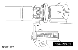
- Calibrate the Anglemaster II Driveline Inclinometer/Protractor by placing it on a clean, flat level section of the frame rail and press the ALT-ZERO button.
Vehicles with flat-flanged, split-pin or slip-flanged U-joints
- NOTE: If equipped, remove the snap ring to allow access to the
base of the U-joint cup. Make sure the Anglemaster II Driveline
Inclinometer/Protractor is seated against the U-joint cup.
NOTE: Rotate the driveshaft until the flange U-joint cup is parallel with the floor. This will simplify taking measurements.
To check the U-joint operating angle, install the Anglemaster II Driveline Inclinometer/Protractor. Check and record the flange angle as angle A.
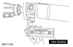
- Using the Anglemaster II Driveline Inclinometer/Protractor, measure the slope of the connecting component. Record the measurement of the component angle as angle B.
Multiple piece driveshafts
- NOTE: Repeat this step for each center support bearing on the
driveshaft.
NOTE: It is not necessary to remove the U-joint snap ring, if equipped, for these measurements.
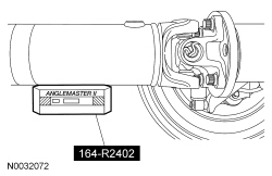
Using the Anglemaster II Driveline Inclinometer/Protractor, measure the slope of the components in front and behind the center support bearing U-joint in the area indicated. Record the front component as angle A and the rear component as angle B.
All vehicles
- NOTE: When 2 connected components slope in the same direction,
subtract the smallest number from the larger number to find the U-joint
operating angle. When 2 connected components slope in the opposite
direction, add the measurements to find the U-joint operating angle.
Calculate the difference in the slope of the components to determine the U-joint operating angle.
- The U-joint operating angle is the angle formed by 2 yokes connected
by a cross and bearing kit. Ideally, the operating angles on each
connection of the driveshaft must:
- be equal or within one degree of each other.
- have a 3 degree maximum operating angle.
- have at least one-half of one degree continuous operating angle.
- The U-joint operating angle is the angle formed by 2 yokes connected
by a cross and bearing kit. Ideally, the operating angles on each
connection of the driveshaft must:
- If the angle is not within specifications, repair or adjust to obtain the correct angle. Inspect the engine mounts, transmission mounts, center support bearing mounting, rear suspension, rear axle, rear axle mounting or the frame for wear or damage.
Driveshaft Runout and Balancing
Special Tool(s)
Driveshaft Inspection
NOTE: Driveline vibration exhibits a higher frequency and lower amplitude than high-speed shake. Driveline vibration is directly related to the speed of the vehicle and is noticed at various speeds. Driveline vibration can be perceived as a tremor in the floorpan or heard as a rumble, hum or boom.
NOTE: Refer to Specifications in this section for all runout specifications.
- NOTE: Do not make any adjustments before carrying out a road
test. Do not change the tire pressure or the vehicle load.
Carry out a visual inspection of the vehicle. Operate the vehicle and verify the condition by reproducing it during the road test.
- The concern should be directly related to vehicle road speed, not affected by acceleration or deceleration or could not be reduced by coasting in NEUTRAL.
- With the vehicle in NEUTRAL, position it on a hoist. For additional
information, refer to Section 100-02.
- The driveshaft should be kept at an angle equal to or close to the curb-weighted position. Use a twin-post hoist or a frame hoist with jackstands.
- Inspect the driveshaft for damage, undercoating or incorrectly seated
U-joints. Rotate the driveshaft slowly by hand and feel for binding or end
play in the U-joint trunnions. Remove the driveshaft. For additional
information, refer to Section 205-01. Inspect the slip yoke splines for any
galling, dirt, rust or incorrect lubrication. Clean the driveshaft or
install new U-joints as necessary. Install a new driveshaft if damaged.
After any corrections or new components are installed, recheck for the
vibration at the road test speed.
- If the vibration is gone, test drive the vehicle.
- If the vibration persists or the driveshaft passes visual inspection, measure the driveshaft runout.
Driveshaft Runout
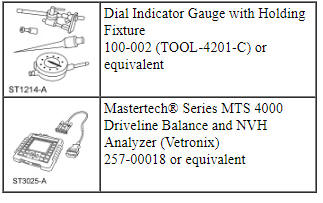
- Install the Dial Indicator Gauge with Holding Fixture. Rotate the
driveshaft by turning the axle and measure the runout at the front, the
center and the rear of the driveshaft.
- If the runout exceeds 1 mm (0.040 in) at the front or center, install a new driveshaft.
- If the front and center is within 1 mm (0.040 in), but the rear runout is not, index-mark the rear runout high point and proceed to Step 2.
- If the runout is within 1 mm (0.040 in) at all points, recheck for vibration at road test speed. If the vibration persists, balance the driveshaft. For additional information, refer to Driveshaft Balancing in this procedure.
- NOTE: Circular pinion flanges can be turned in 90 degree or
one-fourth increments. Half-round pinion flanges are limited to 2 positions.
Index-mark the driveshaft to the pinion flange. Disconnect the driveshaft and rotate it 180 degrees. Reconnect the driveshaft. Recheck the runout at the rear of the driveshaft.
- If the runout is still over specification, mark the high point and proceed to Step 3.
- If the runout is within specification, check for the vibration at the road test speed. If the vibration is still present, balance the driveshaft. For additional information, refer to Driveshaft Balancing in this procedure.
- Excessive driveshaft runout can originate in the driveshaft itself or
from the pinion flange. To find the source, compare the 2 high points
previously determined.
- If the index marks are close together, within 25 mm (1 in), the driveshaft is eccentric. Install a new driveshaft.
- If the marks are on opposite sides of the driveshaft, 180 degrees apart, the slip yoke or pinion flange is responsible. Check the pinion flange runout. If the pinion flange runout exceeds specifications, a bent pinion is indicated.
- If the pinion flange and pinion runouts are within specifications, road test and check for the vibration at the road test speed. If the vibration persists, balance the driveshaft. For additional information, refer to Driveshaft Balancing in this procedure.
Driveshaft Balancing - Using the Mastertech Series MTS 4000 Driveline Balance and NVH Analyzer (Vetronix)
All vehicles
- Install the Mastertech Series MTS 4000 Driveline Balance and NVH Analyzer (Vetronix) to the vehicle.
- Working under the vehicle, install an accelerometer. The accelerometer can be attached and mounted near either the transmission or differential end of the driveshaft.
- Clean an area of the driveshaft and install the reflective tape, then
install the photo-tachometer sensor. The sensor should be placed at
approximately a 20-degree angle from perpendicular to the surface of the
reflective tape. Make sure the sensor does not get moved during the balance
procedure.
- Reflective tape.
- Photo-tachometer sensor.
- Using the Mastertech Series MTS 4000 Driveline Balance and NVH Analyzer (Vetronix), run a driveshaft balance test with the driveshaft unmodified.
Vehicles with tapped pinion flanges
- Label the tapped holes in the pinion flange numerically, starting at the top hole as 1. Mark the remaining holes 2, 3 and 4. Label in the direction of rotation.
- Using the Mastertech Series MTS 4000 Driveline Balance and NVH Analyzer (Vetronix), run a second test with the 12 mm (0.47 in) test weight set screw in the No. 1 hole, previously marked on the pinion flange.
- Remove the test weight, then install the weight combination directed by the Mastertech Series MTS 4000 Driveline Balance and NVH Analyzer (Vetronix).
Vehicles without tapped pinion flanges
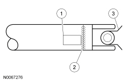
- Using the Mastertech Series MTS 4000 Driveline Balance and NVH Analyzer
(Vetronix), run a second test with a test weight. Using a metal band, secure
the test weight to the end of the driveshaft. The weight should be placed at
the end of the driveshaft tube, as close to the tube-to-yoke weld seam as
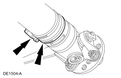
possible. Mark the location of the test weight on the driveshaft, as shown
in the figure below.
- Test weight.
- Tube-to-yoke weld seam.
- Driveshaft pinion flange.
- Select the test weight based on driveshaft size. Larger driveshafts use 10 g (0.353 oz). Smaller driveshafts use 5 g (0.176 oz).
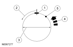
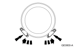
- Remove the test weight, then install the recommended weight at the
position directed by the Mastertech Series MTS 4000 Driveline Balance and
NVH Analyzer (Vetronix). Using a metal band and epoxy, secure the test
weight to the driveshaft, as shown in the figure below.
- Test weight.
- Measure in this direction.
- Driveshaft diameter.
- Directional rotation.
- Balance weight relative to test weight centerline.
- The results are displayed with respect to the location to where the test weight was placed.
All vehicles
- Using the Mastertech Series MTS 4000 Driveline Balance and NVH Analyzer (Vetronix), run a third test to verify the repair.
Driveshaft Balancing - Hose Clamp Method
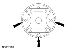
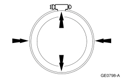
- Install 1 or 2 hose clamps on the driveshaft, near the rear. Position of the hose clamp head(s) can be determined through trial and error.
- Mark the rear of the driveshaft into 4 approximately equal sectors and number the marks 1 through 4. Install a hose clamp on the driveshaft with its head at position No. 1, as shown in the figure below. Check for vibration at road speed. Recheck with the clamp at each of the other positions to find the position that shows minimum vibration. If 2 adjacent positions show equal improvement, position the clamp head between them.
- If the vibration persists, add a second clamp at the same position and recheck for vibration.
- If no improvement is noted, rotate the clamps in opposite directions, equal distances from the best position determined in Step 2. Separate the clamp heads about 13 mm (1/2 in) and recheck for vibration at the road speed.
- Repeat the process with increasing separation until the best combination is found or the vibration is reduced to an acceptable level.
 Driveline
...
 Driveshaft
SPECIFICATIONS
Torque Specifications
DESCRIPTION AND OPERATION
Driveshaft
NOTE: All driveshaft assemblies are balanced. If undercoating the
vehicle, protect the driveshaft to prevent overspra ...
Other materials:
Fuel Charging and Controls - 3.5L GTDI
SPECIFICATIONS
Material
Torque Specifications
a Refer to the procedure in this section.
DESCRIPTION AND OPERATION
Fuel Charging and Controls
3.5L Gasoline Turbocharged Direct Injection (GTDI)
WARNING: Do
not smoke, carry lighted tobacco or have an open flame of any type when working
on or n ...
Steering
Electric Power Steering
WARNING: The electric power steering system has diagnostic
checks that continuously monitor the system to ensure proper
operation. When a system error is detected a steering message will
appear in the information display.
WARNING: The electric power steering system has d ...
General Procedures
Audio Control Module (ACM) Self-Diagnostic Mode
NOTE: If the Audio Front Control Module (ACM) is completely
inoperative (does not power up), the part number decal on the Audio Front
Control Module (ACM) chassis can be used to attain the ACM part number.
Turn the ACM on.
...
