Seat Backrest - Front
Disassembly
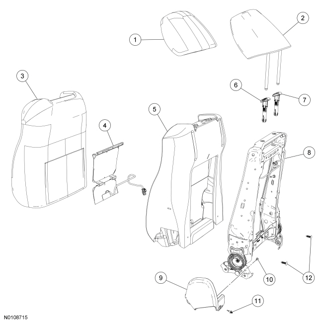
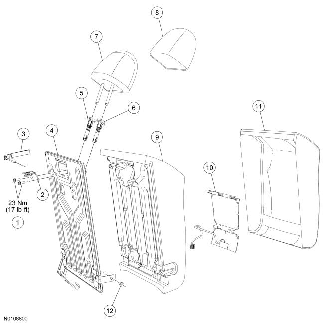
Seat Backrest - Trim Parts
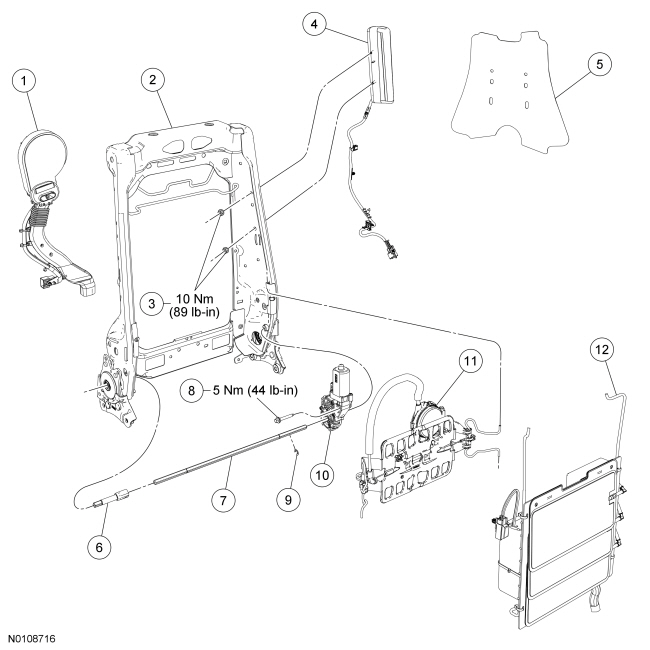
Seat Backrest - Frame Parts With Manual Lumbar and Static Lumbar
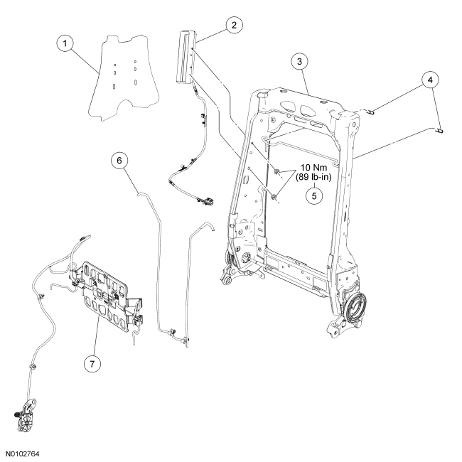
Seat Backrest - Frame Parts With Power Lumbar
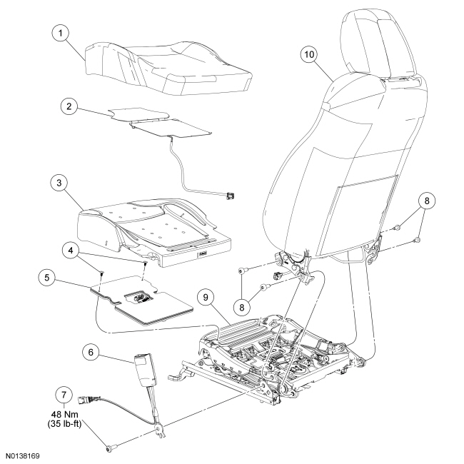
Seat Cushion - With Active Motion
NOTE: Refer to Seat Backrest - Front for recliner-to-seat track bolt tightening sequence and torque specification.
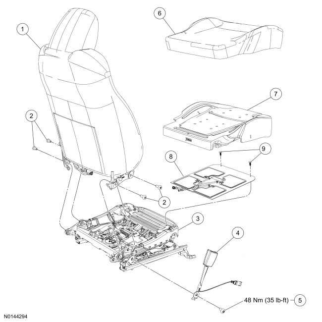
Seat Cushion - Without Active Motion
NOTE: Refer to Seat Backrest - Front in this section for recliner-to-seat track bolt tightening sequence and torque specification.
WARNING: Always carry a live airbag with the deployment door, trim cover or tear seam pointed away from the body. Do not place a live airbag down with the deployment door, trim cover or tear seam facing down. Failure to follow these instructions may result in serious personal injury in the event of an accidental deployment.
WARNING: Front seat backrest trim covers installed on seats equipped with seat side airbags cannot be repaired. A new trim cover must be installed. Cleaning is permissible. Failure to follow these instructions may result in the seat side airbag deploying incorrectly and increase the risk of serious personal injury or death in a crash.
NOTE: If a side air bag deployment took place, a new seat backrest foam pad, backrest trim cover, deployment chute and side air bag module and nuts must be installed. The seat backrest frame should be replaced if necessary.
- Remove the seat backrest. Refer to Seat Backrest - Front.
- Remove the 2 head restraint guides sleeves. Refer to Head Restraint Guide Sleeve - Front.
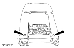
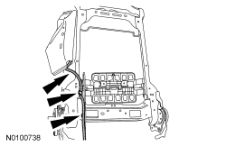
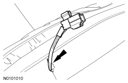
- NOTE: Note wire harness and hose routing for installation.
Detach the backrest cover lower J-clips and route the wire harness(es), manual lumbar cable (if equipped) and air hoses (if equipped) out of the hole(s) in the backrest cover.
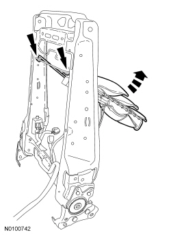
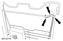
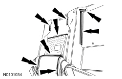
- On each side, separate the backrest cover clip and hook-and-loop strips.
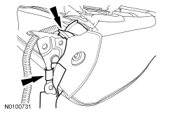
- NOTICE: Use care when separating the backrest cover from the
hook-and-loop strip, or the hook-and-loop strip can be torn from the
backrest foam pad.
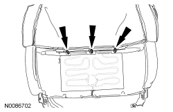
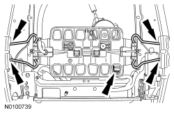
Separate the hook-and-loop strips, invert the backrest cover up and remove the 3 first row hog rings.
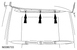
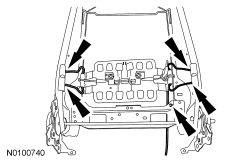
- Separate the hook-and-loop strips, invert the backrest cover up and remove the 3 second row hog rings.
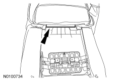
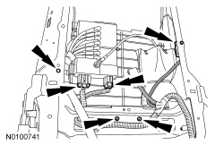
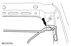
- From the rear of the backrest, detach the backrest cover J-clip attached to the backrest frame wire.
- Invert the backrest cover up, separate the hook-and-loop strips and remove the backrest cover.
- If equipped, detach the backrest Thermo-Electric Device (TED) from the backrest foam pad wire.
- If equipped, disconnect the backrest heater mat electrical connector and separate the pin-type retainer.
- Remove 2 pin-type retainers and the backrest frame assembly from the backrest foam pad.
- If equipped, remove the backrest TED.
- Disconnect the electrical connector and separate the pin-type retainer.
- Detach the TED from the backrest frame wire.
- Remove the TED from between the power lumbar and cable.

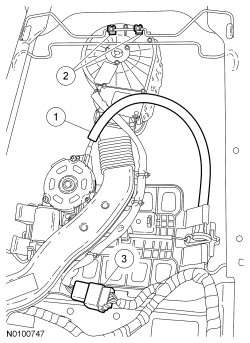
- Separate the side air bag module wire harness retainers from the backrest frame.

- Remove the nuts and the side air bag module with wire harness.
- If necessary, remove the side air bag module from the deployment chute.
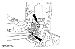
- If equipped, remove the power lumbar.
- Disconnect the motor and detach the retaining clips.
- If equipped, remove the manual lumbar.
- Detach the cable and manual lumbar retainers.
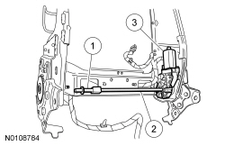
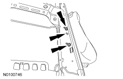
- If equipped, remove the static lumbar in the following sequence.
- Squeeze the retainers together at the bottom and separate from the backrest frame.
- Remove and discard the clips at the top.
- If equipped, disconnect the power lumbar with massage electrical connectors, detach the pin-type retainers and lower retainers.
- If equipped, rotate the assembly up, detach the upper retainers and remove the power lumbar with massage.
Seats with power recliner
- NOTICE: Do not rotate the inboard and outboard recliners
separately from each other. Doing so will cause the recliners to become out
of synchronization.
Remove the E-clip on the recliner shaft and the recliner motor bolt.
- Remove the power recliner motor.
- Slide the recliner shaft assembly out of the recliner and remove the short recliner shaft.
- Slide the long recliner shaft out of the recliner motor.
- Disconnect and remove the power recliner motor.
All seats
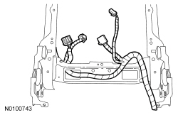
- NOTE: Note wire harness routing for installation.
If equipped, remove the backrest wire harness.
Assembly
- NOTE: Wire harness may differ due to option content.
If equipped, position the backrest wire harness and attach the retainers.
- If equipped, install the recliner motor in the following sequence.
- Slide the long recliner shaft into the recliner motor and recliner.
- Connect the recliner motor.
- Slide the short recliner shaft onto the long recliner shaft.
- Slide the recliner shaft assembly into the recliner on the other side.
- Position the recliner motor and install the bolt.
- Tighten to 5 Nm (44 lb-in).
- Install the E-clip on the recliner shaft recession, near the recliner motor.
- If equipped, engage both power lumbar with massage wires and rotate the assembly down.
- If equipped, install the power lumbar with massage lower retainers, connect the electrical connectors and attach the pin-type retainers.
- If equipped, position the static lumbar and install the retainers at the bottom.
- Position the static lumbar in front of the backrest frame wire and
install 2 new retainers.
- After installation, make sure the retainers are holding the static lumbar tightly against the backrest frame wire or squeaks can occur.
- If equipped, attach the manual lumbar retaining clips and cable retainer.
- If equipped, attach the power lumbar retaining clips and connect the electrical connector.
- NOTE: Passenger side shown, driver side similar.
Position the side air bag module into the deployment chute.
- Route the side air bag module wire harness through the deployment chute.
- Position the 2 side air bag module studs and locator pin through the deployment chute holes.
- NOTE: The side air bag modules are keyed left and right. If the
side air bag module locator pin does not align to the backrest frame hole,
the wrong side air bag module is being installed.
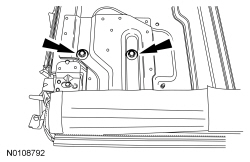
Position the 2 side air bag module studs and locator pin through the backrest frame and install the 2 nuts.
- Tighten to 10 Nm (89 lb-in).
- Route and attach the side air bag module wire harness to the backrest frame.
- If equipped, install the backrest TED.
- Position the TED between the power lumbar and cable.
- Attach the TED upper retainers to the backrest frame wire.
- Connect the electrical connector and attach the pin-type retainer.
- WARNING:
Inspect the seat side air bag module cavity in the seat backrest foam pad
for any foreign material. If any foreign material is found, remove it.
Failure to follow these instructions may result in the seat side air bag
module deploying incorrectly and increases the risk of serious personal
injury or death in a crash.
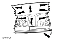
Position the backrest frame assembly into the backrest foam pad. Install 2 pin-type retainers.
- If equipped, connect the backrest heater mat electrical connector and attach the pin-type retainer.
- If equipped, attach the backrest TED to the backrest foam pad wire.
- WARNING:
If the seat side air bag module deployment chute is not correctly
positioned, the seat side air bag may not deploy correctly. Failure to
follow this instruction may result in the seat side air bag deploying
incorrectly, which increases the risk of serious personal injury or death in
a crash.
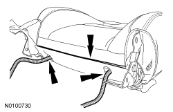
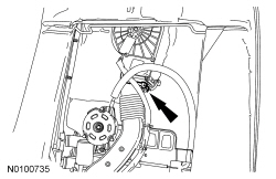
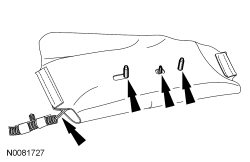
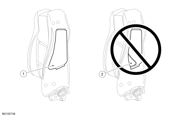
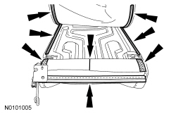
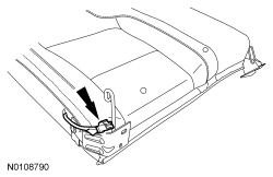
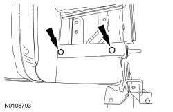
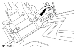
NOTE: The seat side air bag module must have a clear exit path from the front of the deployment chute. Both deployment chute front edges must be positioned to lay flat when positioned between the backrest foam pad and backrest frame.
NOTE: Illustration shown looking through the side of the backrest foam pad and at the side air bag module deployment chute.
Check the position of the deployment chute.- Position both deployment chute front edges to lay flat, from top to bottom, between the backrest foam pad and backrest frame.
- Do not allow the deployment chute front edges to fold over, at any point, between the backrest foam pad and backrest frame.
- With the backrest cover inside out, position it to the backrest foam pad
and frame assembly.
- Align the head restraint holes in the backrest cover to the holes in the backrest foam pad and frame.
- Roll the backrest cover down, attach the hook-and-loop strips and the J-clip at the rear to the backrest frame wire.
- Roll the backrest cover down, attach the hook-and-loop strips and install the 3 second row hog rings.
- Roll the backrest cover down, attach the hook-and-loop strips and install the 3 first row hog rings.
- Roll the backrest cover down and attach the hook-and-loop strips.
- Route the wire harness(es) and air hoses (if equipped) through the
hole(s) in the backrest cover and attach the lower J-clips.
- Make sure the manual lumbar cable is routed out from the outboard side of the backrest before engaging the lower J-clips (if equipped).
- On each side, wrap the backrest cover around the recliner and attach the hook-and-loop strips and clip.
- Install the 2 head restraint guides sleeves. Refer to Head Restraint Guide Sleeve - Front.
- Install the seat backrest. Refer to Seat Backrest - Front.
Seat Backrest - Rear, 40 Percent
Disassembly
NOTICE: Do not reinstall any heater mat or foam pad after removal. The adhesive will not adhere correctly to the foam pad, causing it to bunch up or shift out of place. A new heater mat and a new foam pad must be installed. Failure to follow these instructions can result in heated seat component damage and system failure.
- Remove the rear seat backrest. For additional information, refer to Seat Backrest - Rear in this section.
- Remove the 2 head restraint guide sleeves. For additional information, refer to Head Restraint Guide Sleeve - Front in this section.
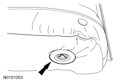
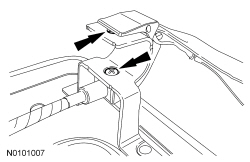
- Release the tabs and remove the pivot grommet.
- If equipped, separate the heater mat electrical connector.
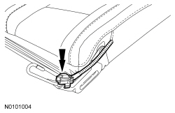
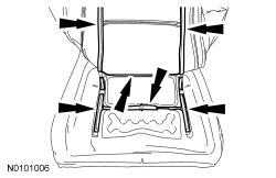
- Disengage the backrest cover J-clip at the bottom, separate the hook-and-loop strips and disengage the retainers on each side.
- Remove the backrest frame from the foam pad.
- Route the latch release strap out of the backrest cover.
- NOTICE: Use care when separating the backrest cover wires from
the backrest foam pad clips, or the clips can be torn from the backrest foam
pad.
NOTICE: Use care when separating the backrest cover from the hook-and-loop strip, or the hook-and-loop strip may be torn from the backrest foam pad.
Release the hook-and-loop strips, disengage the wires from the clips and remove the backrest cover.- Route the heated seat mat pigtail and connector out of the backrest cover (if equipped).
- If a new backrest foam pad or backrest heater mat is to be installed,
obtain a new backrest foam pad and a new backrest heater mat.
- Do not remove the old backrest heater mats from the old backrest foam pad and reuse any of these parts.
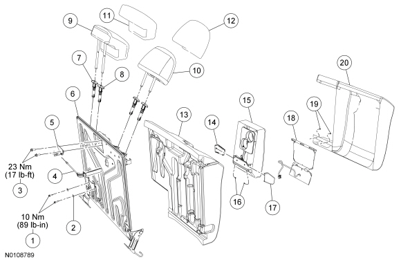
- Disengage the 2 cable retainers, remove the 2 bolts and latch.

Assembly
- Position the latch, install the 2 bolts and engage the 2 cable
retainers.
- Tighten to 23 Nm (17 lb-ft).
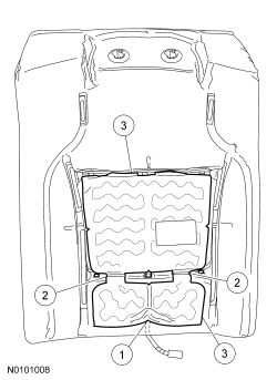
- Install a new backrest heater mat onto a new backrest foam pad.
- Route the backrest heater mat pigtail and electrical connector through the backrest foam pad to the other side.
- Position the backrest heater mat onto the backrest foam pad so the
opening aligns to the clips in the backrest foam pad.
- Tuck the backrest heater mat into the backrest foam pad trench.
- Make sure the backrest heater mat stays in place, remove the paper strips from under the backrest heater mat and adhere to the backrest foam pad, laying it flat with no wrinkles.
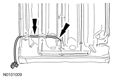
- Route the heater mat wire harness in the foam pad trench.
- Position the backrest cover to the backrest foam pad. Attach the wires
to the clips and the hook-and-loop strips.
- Route the heated seat mat wire harness and connector through the backrest cover (if equipped).

- Position the backrest frame into the foam pad.
- Route the latch release strap through the backrest cover.

- Attach the backrest cover hook-and-loop strips and engage the retainers on each side.
- Engage the backrest cover J-clips and hook-and-loop strips at the
bottom.
- Attach the heater mat electrical connector (if equipped).
- Install the pivot grommet.
- Install the 2 head restraint guide sleeves. For additional information, refer to Head Restraint Guide Sleeve - Front in this section.
- Install the rear seat backrest. For additional information, refer to Seat Backrest - Rear in this section.
Seat Backrest - Rear, 60 Percent
Disassembly
NOTICE: Do not reinstall any heater mat or foam pad after removal. The adhesive will not adhere correctly to the foam pad, causing it to bunch up or shift out of place. A new heater mat and a new foam pad must be installed. Failure to follow these instructions can result in heated seat component damage and system failure.
- Remove the rear seat backrest. For additional information, refer to Seat Backrest - Rear in this section.
- Remove the 4 head restraint guide sleeves. For additional information, refer to Head Restraint Guide Sleeve - Front in this section.
- If equipped, separate the heater mat electrical connector.
- Disengage the backrest cover J-clip at the bottom, separate the hook-and-loop strips and disengage the retainers on each side.
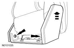
- Remove the 2 bolts and armrest with bracket.
- Remove the 2 pin-type retainers at the armrest pocket.
- Remove the backrest frame from the foam pad.
- NOTICE: Use care when separating the backrest cover wires from
the backrest foam pad clips, or the clips can be torn from the backrest foam
pad.
NOTICE: Use care when separating the backrest cover from the hook-and-loop strip, or the hook-and-loop strip may be torn from the backrest foam pad.
Release the hook-and-loop strips, disengage the wires from the clips and remove the backrest cover.- Route the heated seat mat wire harness and connector out of the backrest cover (if equipped).
- If a new backrest foam pad or backrest heater mat is to be installed,
obtain a new backrest foam pad and a new backrest heater mat.
- Do not remove the old backrest heater mats from the old backrest foam pad and reuse any of these parts.
- Disengage the 2 cable retainers, remove the 2 bolts and latch.
- Remove the screw at each armrest side cover, slide up and remove.
Assembly
- Position the armrest side covers, slide down and install the screws.
- Position the latch, install the 2 bolts and engage the cable retainers.
- Tighten to 23 Nm (17 lb-ft).
- Install a new backrest heater mat onto a new backrest foam pad.
- Route the backrest heater mat pigtail and electrical connector through the backrest foam pad to the other side.
- Position the backrest heater mat onto the backrest foam pad so the
opening aligns to the clips in the backrest foam pad.
- Tuck the backrest heater mat into the backrest foam pad trench.
- Make sure the backrest heater mat stays in place, remove the paper strips from under the backrest heater mat and adhere to the backrest foam pad, laying it flat with no wrinkles.

- Route the heater mat wire harness in the foam pad trench.

- Position the backrest cover to the backrest foam pad. Attach the wires
to the clips and the hook-and-loop strips.
- Route the heated seat mat wire harness and connector through the backrest cover (if equipped).
- Position the backrest frame into the foam pad.
- Route the latch release strap through the backrest cover.
- Install the 2 pin-type retainers at the armrest pocket.
- Position the armrest with bracket to the backrest frame and install the
2 bolts.
- Tighten to 10 Nm (89 lb-in).
- Attach the backrest cover hook-and-loop strips and engage the retainers on each side.
- Engage the backrest cover J-clips and hook-and-loop strips at the
bottom.
- Attach the heater mat electrical connector (if equipped).
- Install the 4 head restraint guide sleeves. For additional information, refer to Head Restraint Guide Sleeve - Front in this section.
- Install the rear seat backrest. For additional information, refer to Seat Backrest - Rear in this section.
 Removal and Installation
Seat - Front
NOTE: Refer to the installation steps for tightening sequence and
torque specification.
NOTE: Passenger seat shown, driver seat similar.
Removal
NOTE: The Supplemental R ...

Other materials:
Changing the vehicle battery
WARNING: Batteries normally produce explosive gases which
can cause personal injury. Therefore, do not allow flames, sparks
or lighted substances to come near the battery. When working near the
battery, always shield your face and protect your eyes. Always provide
proper ventilation.
WARNING: W ...
General Procedures
Solenoid Body Identification Procedure
Original Solenoid Body Service Tag
Using the scan tool, select Powertrain, Transmission and Transmission
Solenoid Body Identification from the toolbox icon and follow the
instructions displayed on the scan tool.
The solenoid body identification screen di ...
Fuel cut-off switch
WARNING: Failure to inspect and if necessary repair fuel leaks
after a collision may increase the risk of fire and serious injury.
Ford Motor Company recommends that the fuel system be inspected by
an authorized dealer after any collision.
In the event of a moderate to severe collision, this v ...
